
Gas compressor and gas compressor blade

A compressor and blade technology, which is applied to machines/engines, mechanical equipment, liquid fuel engines, etc., can solve the problems of increased secondary flow loss, increased angular vortex strength, and decreased compressor flow and performance, and achieves a reduction in two The effect of secondary flow loss, reduction of low speed area, and improved performance

Active Publication Date: 2020-12-08
AECC COMML AIRCRAFT ENGINE CO LTD
View PDF6 Cites 0 Cited by
  • Summary
  • Abstract
  • Description
  • Claims
  • Application Information

AI Technical Summary

Problems solved by technology

[0003] According to the research of the inventor, after adding the chamfered structure of the moving and static blades to the multi-stage axial compressor, under the action of the chamfering, the distribution of the vortex system in the cascade flow field changes, the vortex in the upper and lower channels migrates to the direction of the middle blade span, and the end The strength of the corner vortex at the wall increases, and the secondary flow loss increases. When the chamfer radius increases to a certain extent, the flow rate and performance of the compressor will decrease significantly

Method used


Image

  • Gas compressor and gas compressor blade
  • Gas compressor and gas compressor blade
  • Gas compressor and gas compressor blade

Examples


Embodiment Construction

[0025] A variety of different implementations or examples for implementing the described subject technical solutions are disclosed below. In order to simplify the disclosure, the following describes the specific examples of each component and arrangement, of course, these are only examples, not limiting the protection scope of the present invention. For example, the description that the first feature described later in the description is formed on or above the second feature may include an embodiment in which the first and second features are formed through direct contact, and may also include an embodiment in which the first and second features are formed between the first and second features. Embodiments of additional features such that there may be no direct relationship between the first and second features. Additionally, reference numerals and / or letters may be repeated in different instances in these disclosures. This repetition is for brevity and clarity and does not i...


PUM


Abstract

The invention aims to provide a gas compressor blade. Compared with an existing gas compressor blade, the gas compressor blade can obtain relatively better aerodynamic performance. The invention further aims to provide a gas compressor which comprises the gas compressor blade. In order to achieve the purpose, the gas compressor blade comprises a blade body and an edge plate connected with the blade top or the blade root of the blade body, the connecting position of the blade body and the edge plate is in transition through a rounded corner, the rounded corner adopts a small chamfer radius at the front edge of the blade body, and a chamfer radius is gradually increased from the front edge of the blade body to the tail edge of the blade body.

Description

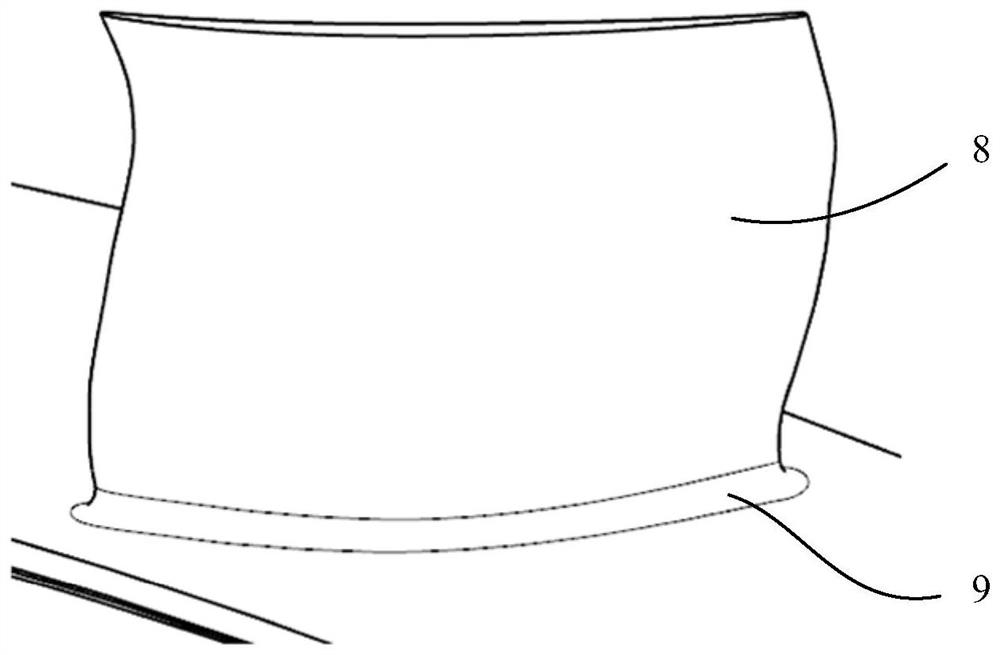
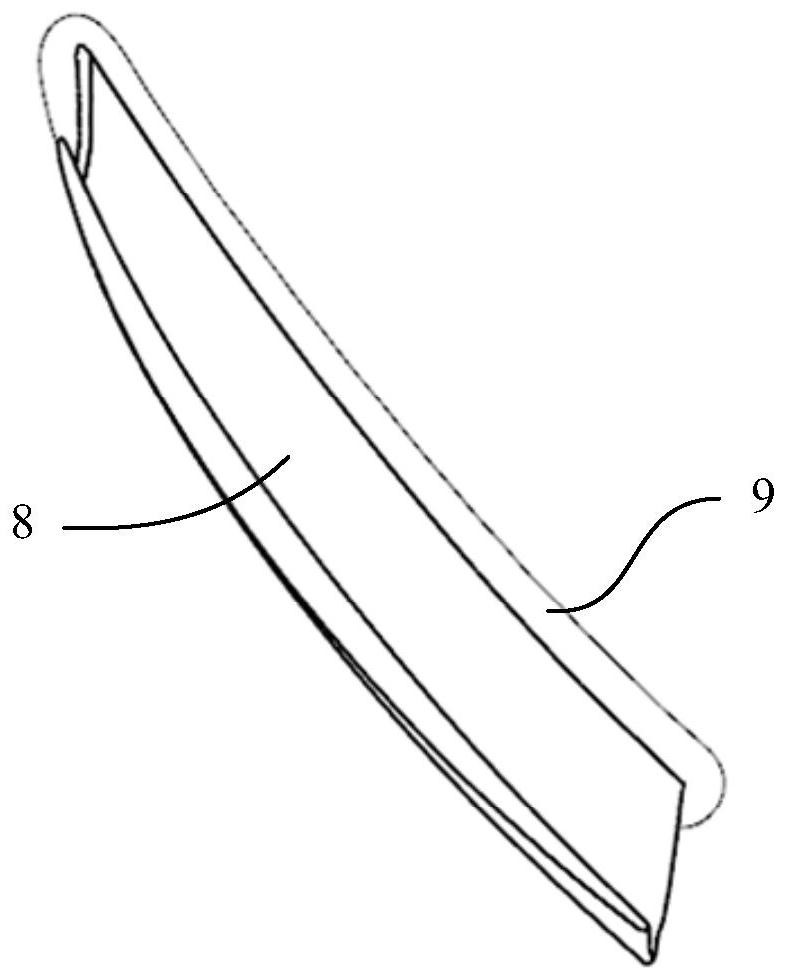
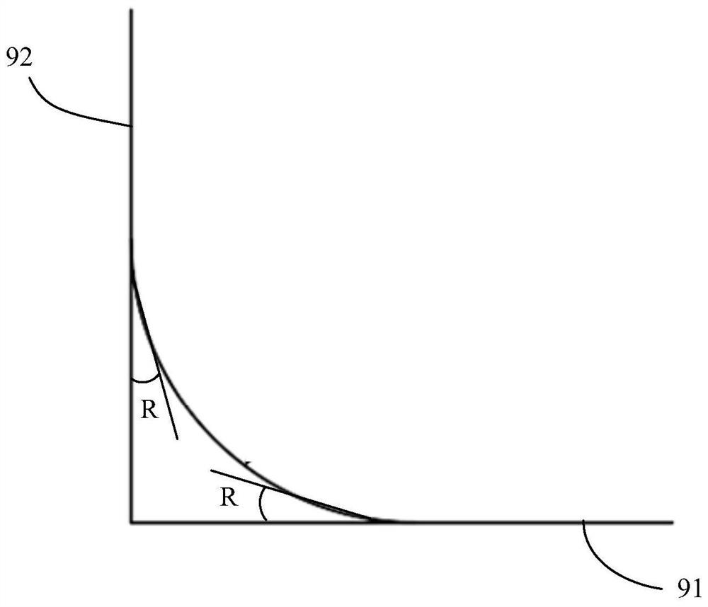
technical field [0001] The present invention relates to compressors and blades thereof. Background technique [0002] In the actual axial flow compressor, due to the influence of processing technology and strength factors, the root of the moving blade and the root tip of the stationary blade are usually chamfered, such as figure 1 as well as figure 2 The three-dimensional schematic view and the top view schematic view of the existing blades are respectively shown. It can be seen from the figure that figure 1 as well as figure 2 The blades 8 shown in all have chamfers 9, and these chamfers 9 are symmetrical structures as shown in the figure. image 3 A schematic diagram is defined for the shape of the existing rounded corner of the blade. The shape of the chamfer 9 is as shown in the figure, which is equal to the included angle R formed by the end wall 91 and the airfoil surface 92 . [0003] According to the research of the inventor, after adding the chamfered structur...

Claims


Application Information

Patent Timeline
Patent Type & Authority Applications(China)
IPC IPC(8): F04D29/38F04D29/66
CPCF04D29/386F04D29/667
Inventor 强艳张晓诗吴帆杨俊曹艺
Owner AECC COMML AIRCRAFT ENGINE CO LTD
Learn More