
Blade wheel structure of multiple wing type centrifugal blower fan

A centrifugal fan, multi-blade technology, used in mechanical equipment, non-variable-capacity pumps, machines/engines, etc., can solve the problem of uneven distribution of outlet speed along the axial direction, and achieve improved fan efficiency and uniform airflow speed distribution. , the effect of simple structure and shape

Inactive Publication Date: 2011-06-01
XI AN JIAOTONG UNIV
View PDF0 Cites 0 Cited by
  • Summary
  • Abstract
  • Description
  • Claims
  • Application Information

AI Technical Summary

Problems solved by technology

[0005] In order to solve the problem of uneven axial distribution of the outlet speed of the existing fan impeller, reduce the secondary flow loss, improve the efficiency of the fan, and reduce noise, the present invention provides a multi-wing fan that makes the axial distribution of the flow velocity at the outlet of the impeller uniform. Centrifugal fan impeller structure

Method used


Image

  • Blade wheel structure of multiple wing type centrifugal blower fan
  • Blade wheel structure of multiple wing type centrifugal blower fan
  • Blade wheel structure of multiple wing type centrifugal blower fan

Examples


Embodiment 1

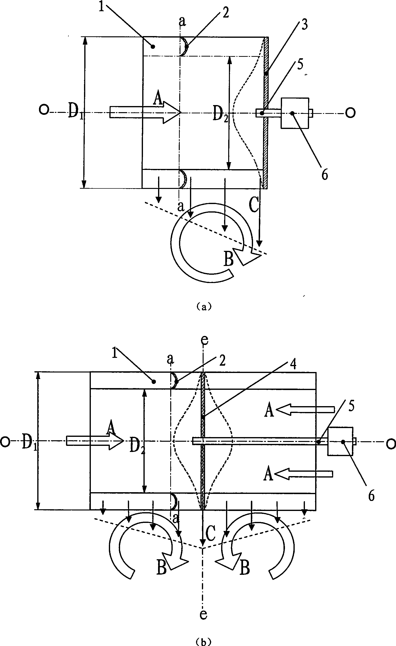
[0024] Such as Figure 4 As shown, the chord length of the impeller blade 1 changes from the cover side (the side of the impeller inlet airflow direction A) to the disk side (the side of the disk 3 or the middle disk 7), and the outer diameter of the impeller changes from D 1 reduce to D 3 , but the inner diameter of the impeller D 2 It remains the same from the lid side to the pan side. From the impeller cover side to the disk side, the chord length of the blade decreases gradually, and the working ability of the blade decreases, thereby reducing the airflow outlet velocity at the impeller disk side, so that the distribution of the airflow velocity C at the impeller outlet along the axial direction tends to be uniform. The straight line a-a where the airfoil chord line is located is perpendicular to the impeller rotation axis O-O.

Embodiment 2

[0026] Such as Figure 5 As shown, similar to Embodiment 1, the impeller blades 1 become chord-length from the cover side to the disc side, but the impeller outer diameter D 1 It remains the same from the cover side to the disc side, and the inner diameter of the impeller changes from the cover side to the disc side by D 2 increase to D 4 . From the impeller cover side to the disk side, the chord length of the blade gradually decreases, and the working ability of the blade decreases, thereby reducing the airflow outlet velocity on the disk side, and making the airflow velocity distribution of the impeller outlet along the axial direction tend to be uniform. The straight line a-a where the airfoil chord line is located is perpendicular to the impeller rotation axis O-O.

Embodiment 3

[0028] Such as Figure 6 As shown, similar to Embodiment 1, the chord length of the impeller blade 1 changes from the cover side to the disk side, and the inner diameter of the impeller changes from D to the disk side. 2 increase to D 4 , the outer diameter of the impeller from the cover side to the disc side by D 1 reduce to D 3 . From the impeller cover side to the disc side, the chord length of the blade decreases gradually, and the working ability of the blade decreases. Therefore, the velocity at the outlet of the airflow at the side of the impeller disk is reduced, and the velocity distribution of the airflow at the outlet of the impeller tends to be uniform along the axial direction. The straight line a-a where the airfoil chord line is located is perpendicular to the impeller rotation axis O-O.


PUM


Abstract

The invention discloses an impeller structure of a multi-wing centrifugal fan, comprising an impeller consisting of a plurality of aerofoil blades. The impeller structure is characterized in that: the chord length of the blade gradually reduces from the side of an impeller cover to the side of an impeller disk, or the chord length of the blade remains the same while the diameter of the impeller gradually reduces, thus leading to the result that the work capability of the blade along the side of the impeller cover to the side of the impeller disk gradually reduces. The impeller structure improved by the invention leads airflow speed of an outlet of the impeller to be more uniform distribution along the axial direction, reduces the secondary flow in a scroll casing, decreases flow losses, improves fan efficiency and reduces noise level. The impeller structure of the invention is simple in form, convenient in processing and low in manufacturing cost.

Description

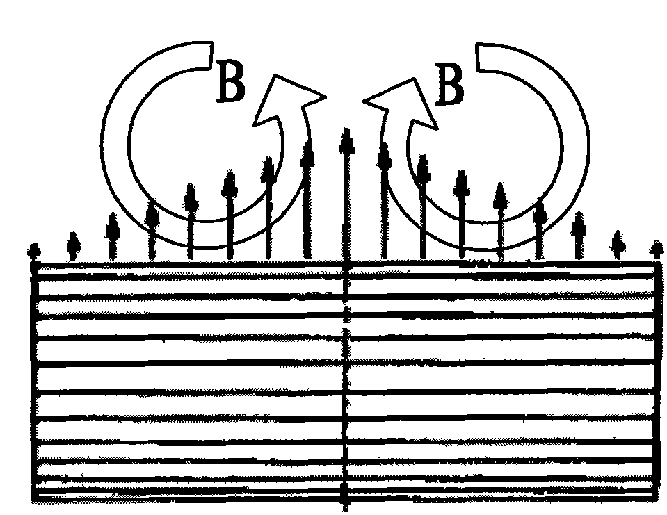
technical field [0001] The invention relates to an impeller structure of a centrifugal fan, in particular to an impeller structure of a multi-blade centrifugal fan. Background technique [0002] The multi-blade centrifugal fan has small size, large flow coefficient, high pressure coefficient and low noise, and is widely used in ventilation devices, electronic equipment, air conditioning and other systems. However, the flow loss of this type of fan is large, and the efficiency is generally low. [0003] At present, multi-blade centrifugal fans mostly adopt the impeller structure of equal-chord straight blades, such as figure 1 As shown, that is, the inlet and outlet edges of the blade are parallel to the rotation axis of the impeller, and the size and shape of each section along the span direction are the same. This type of blade is simple to manufacture and low in production cost. However, due to the different airflow velocities at the blade inlet along the span direction,...

Claims


Application Information

Patent Timeline
Patent Type & Authority Patents(China)
IPC IPC(8): F04D29/26F04D29/30F04D29/66
Inventor 宫武旗张伟席光邓俊杰
Owner XI AN JIAOTONG UNIV
Learn More