Air channel flap and flow guiding device

a technology of air channel flaps and guide devices, which is applied in the direction of heating types, ventilation systems, vehicle cleaning, etc., can solve the problems of ventilation and air conditioning devices, the inability to arrange flaps of large size, and the lack of free flow lengths

Inactive Publication Date: 2009-12-01
BEHR GMBH & CO KG
View PDF28 Cites 8 Cited by
  • Summary
  • Abstract
  • Description
  • Claims
  • Application Information

AI Technical Summary

Benefits of technology

[0007]The object of the invention is to provide a flap for air ducts which makes it possible to switch or divide an air stream to or be...

Problems solved by technology

Furthermore, the construction space required in this case depends on how large a design the flap has.
On the other hand, it is also troublesome when large construction spaces are taken up for switching devices.
Large construction spaces and free ...

Method used


Image

  • Air channel flap and flow guiding device
  • Air channel flap and flow guiding device
  • Air channel flap and flow guiding device

Examples


Embodiment Construction

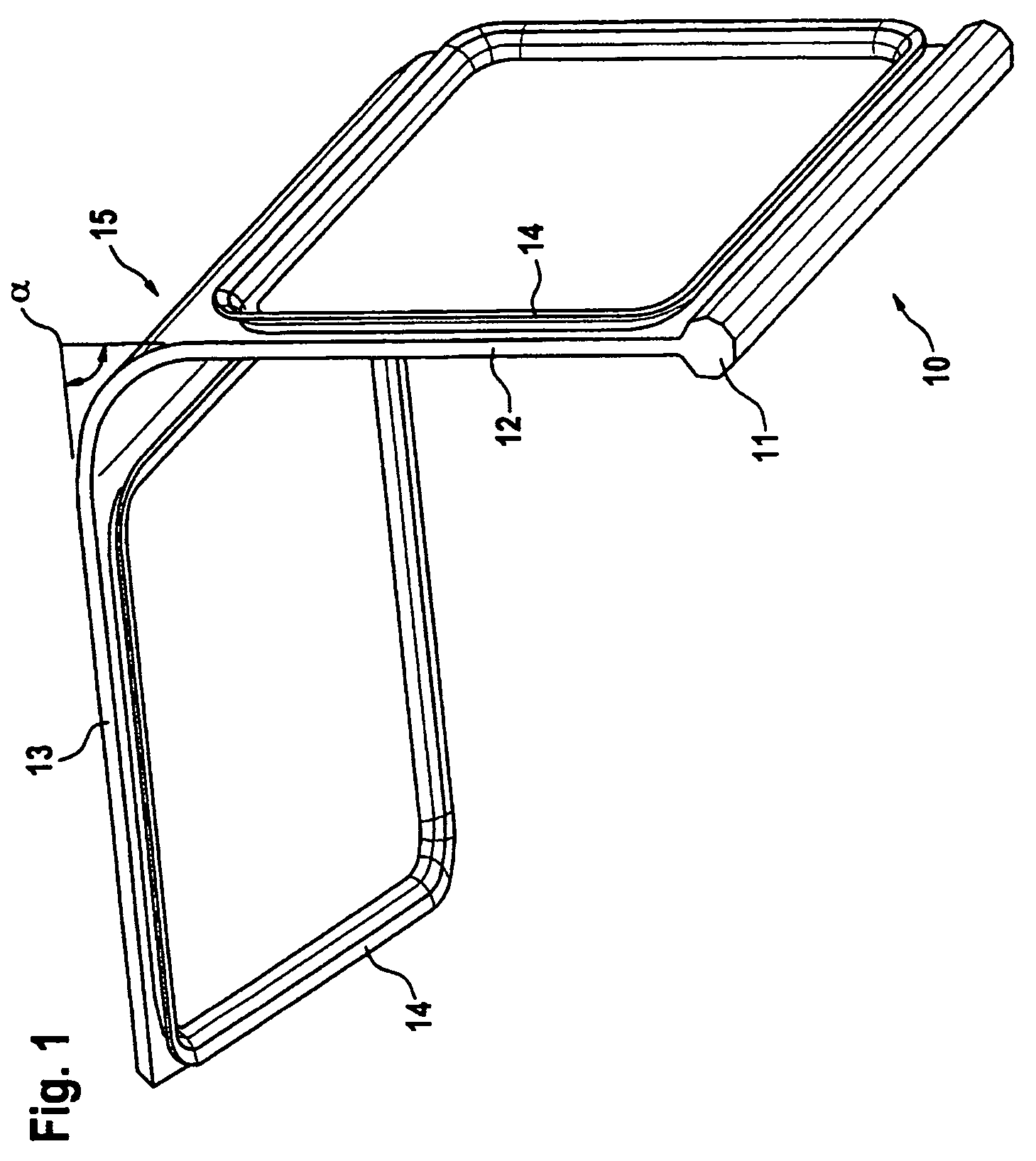
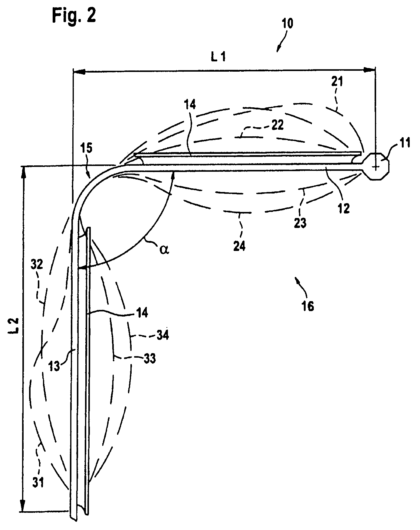
[0024]FIGS. 1 and 2 show a flap 10 respectively in a perspective and in a cross-sectional illustration. The flap 10 is formed from the pivot axis 11 and the projecting flap segments 12 and 13. The flap segment 12 directly adjoins the pivot axis 11 and forms the proximal flap segment 12, while the further flap segment 13 is arranged distally with respect to the pivot axis 11 with respect to the first flap segment 12. Each of the flap segments has a sealing profile 14 which forms a closed contour line on the surface of the corresponding flap segments 12 and 13.

[0025]FIG. 1 shows a flap in which the two flap segments 12 and 13 are designed as planar sheetlike elements, and, to produce the generally concave shape, there is formed at the transition between the two elements a bending point 15 at which the two flap segments 12 and 13 have an internal angle α which is smaller than 180°. In the exemplary embodiment illustrated, the internal angle is a right angle.

[0026]FIG. 2 shows, as a mai...


PUM


Abstract

The invention relates to a flap (10) for air channels provided with a multi-flow conduit arranged downstream with respect to said flap, airflows (45, 46) being limited by flow guiding elements (56, 57), and thereby separated from each other. According to said invention, the axis of rotation (11) of the flap is arranged on the edge, the flap being transversally projected with respect to the axis and divided into two flap segments which are arranged one after another. Each flap segment is provided with at least one sealing device (14) for airtight seating against a passage opening.

Description

BACKGROUND OF THE INVENTION[0001]The present invention relates to a flap for air ducts and to a flow guide device, such as is generally known.[0002]In air ducts, flaps are used to switch multi-conduit flow lines located downstream of the flap. The flaps may in this case serve, on the one hand, for a continuous variable distribution of the air streams between the downstream conduits or else also for a complete alternating changeover of the fluid path of the air stream between the various conduits.[0003]Thus, correspondingly designed flaps have sealing devices which, in cooperation with throughflow orifices present on the flow guide devices, can provide leaktight bearing contact, so that conduits can be closed off in a fluidtight manner.[0004]Such flaps for controlling the ducts take up a specific construction length in the throughflow direction of the air. This construction length is determined essentially by the dimensions of the flap and by the construction space required for adjus...

Claims


Application Information

Patent Timeline
IPC IPC(8): B60H1/00F24F7/007
CPCB60H1/00678B60H2001/00721Y10T137/87812
Inventor KOMOWSKI, MICHAEL
Owner BEHR GMBH & CO KG
Why Eureka
Try Eureka