Carbon black reactor

a carbon black reactor and reactor technology, applied in the field of carbon black reactors, can solve the problems of difficult to obtain the characteristics of one produced in the pilot-scale plant, and achieve the effect of improving conversion ratio and contact efficiency

Inactive Publication Date: 2009-12-01
ASAHI CARBON
View PDF7 Cites 13 Cited by
  • Summary
  • Abstract
  • Description
  • Claims
  • Application Information

AI Technical Summary

Benefits of technology

[0015]The purpose of the present invention is to solve the scanty output of a carbon black, which is the largest defect of the production in the pilot-scale reactor, while the contact efficiency between the hot combustion gas and the feedstock is maintained high.
[0016]Therefore, first subject of the present invention is to provide a novel carbon black reactor which increases the contact efficiency between the hot combustion gas and the feedstock to improve the conversion rate from the feedstock to the carbon black. Second subject of the present invention is to provide a novel carbon black reactor which produces a carbon black characterized that the distribution of an aggregate, which is the smallest dispersion unit to a rubber matrix, is narrower than a common product in a large scale production at a low cost.
[0023]In the present invention, the cross-section shape of the reaction chamber, especially at feedstock introduction part, is not a circle nor a polygon, in addition, there is a difference in length between the longest axis and the shortest axis. At feedstock introduction part, feedstock atomizing means are arranged at proper locations so as not to make any space in which a hot combustion gas does not contact with the feedstock streams and passes to the downstream, particularly in a central region of the reaction zone. Thus, a contact efficiency between the hot combustion gas and the feedstock is increased to improve a conversion ratio from the feedstock to the carbon black.

Problems solved by technology

As mentioned above, when a carbon black is produced in the reactor actually operated, it is very difficult to obtain the product having the characteristics of one produced in the pilot-scale plant.

Method used


Image

  • Carbon black reactor
  • Carbon black reactor
  • Carbon black reactor

Examples


example 1

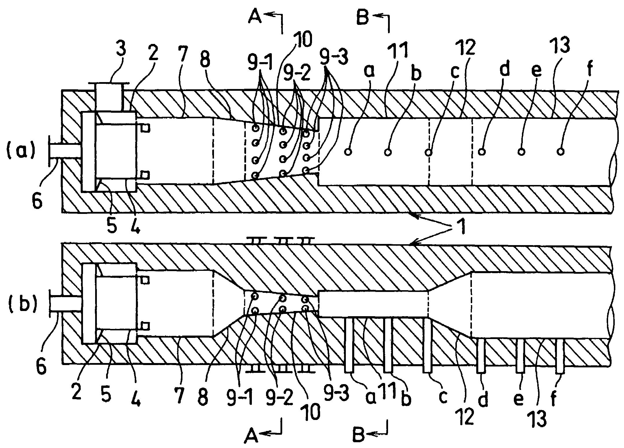
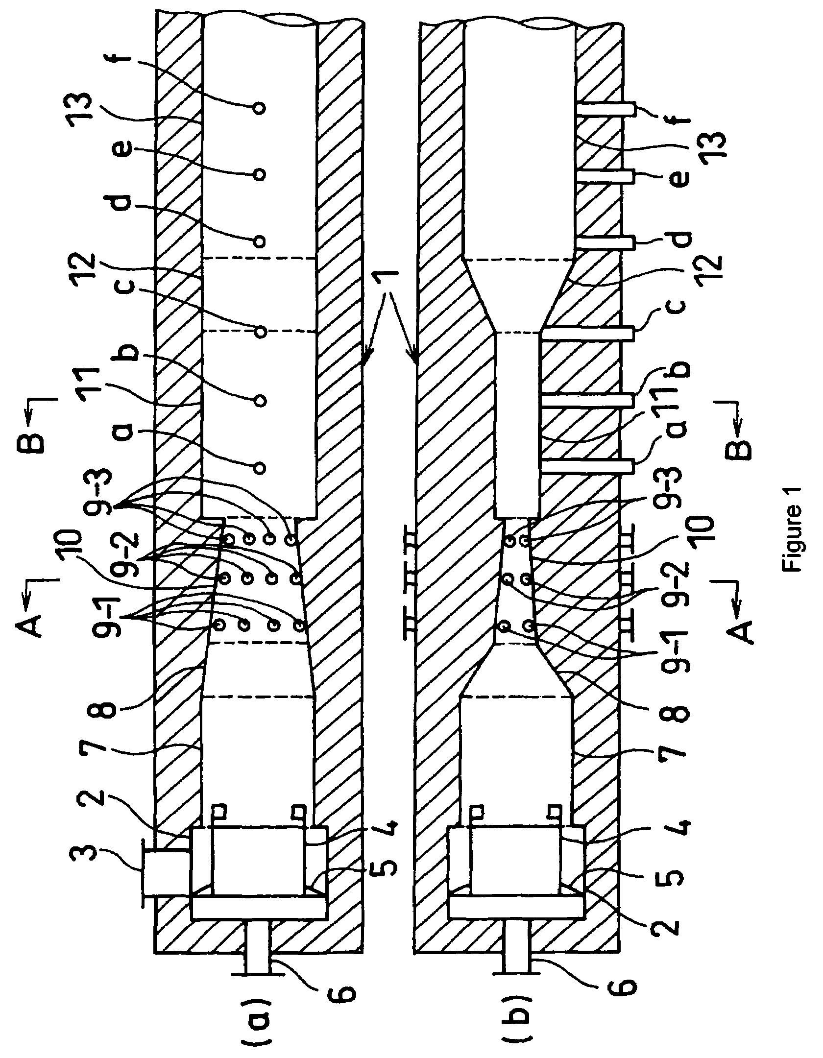
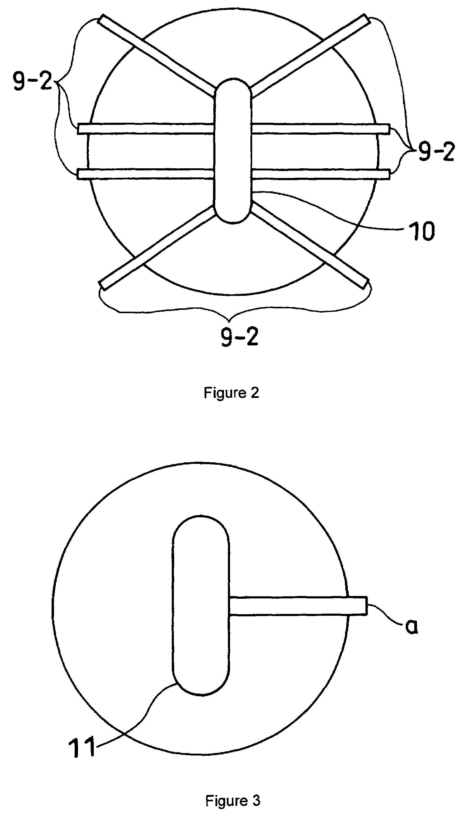
[0047]A SAF carbon black was produced by using the carbon black reactor having structure as shown in FIGS. 1, 2 and 3. The dimensions of the each element in the reactor were as follows. In the case where the cross-section shape of the element is a torus, the dimensions of it is shown in the length of the major axis (longest length, x) and the length minor axis (shortest length, y).[0048]Hydrocarbon Fuel Introduction Chamber 2[0049]Inside diameter: 650 mm[0050]Length: 600 mm[0051]Oxygen Containing Gas Introduction Conduit 3[0052]Long side: 400 mm[0053]Short side: 200 mm[0054]Oxygen Containing Gas Conduit 4[0055]Inside diameter: 450 mm[0056]Length: 500 mm[0057]Combustion Chamber 7[0058]Inside diameter: 595 mm[0059]Length: 1000 mm[0060]Intermediate Conversion Chamber 8[0061]Cross-section shape at upstream end: circle, 595 mm[0062]Cross-section shape at downstream end: torus, x=472 mm, y=241 mm[0063]Length: 500 mm[0064]Convergence angle in the vertical direction: 7°[0065]Convergence ang...

example 2

[0091]A SAF carbon black was produced by using same reactor as Example 1 except that different feedstock introduction part was used.[0092]Feedstock Introduction Part 9-3[0093]100 mm upstream from down stream end of the reaction chamber 10[0094]Cross-section shape: torus, x=327 mm, y=95 mm[0095]Length ratio (x / y): 3.42[0096]Number of feedstock atomizing means: 8


PUM

PropertyMeasurementUnit
center angleaaaaaaaaaa
convergence angleaaaaaaaaaa

Abstract

This invention relates to a carbon black reactor comprising; a combustion zone for generating a hot combustion gas by burning a mixture of a hydrocarbon fuel and an oxygen containing gas, a reaction zone for producing a carbon black by contacting the hot combustion gas with a feedstock introduced in a plurality of divided flows to thermally decompose and / or incompletely combust the feedstock, and a quench zone for stopping a carbon black growth reaction by injection a coolant to said carbon black containing flow, and these three zones are arrayed laterally in order, wherein the cross-section shape of the feedstock introduction part in the reaction zone is not a circle nor a polygon. The carbon black reactor can produce the carbon black having same characteristics, especially the distribution of the aggregate size, as one produced by pilot-scale reactor, while its production scale is increased to the level of that of reactor actually operated.

Description

TECHNICAL FIELD[0001]This invention relates to a carbon black reactor, and more particularly to a carbon black reactor having the feedstock introduction part of a novel cross-section shape for modifying the manner of a contact between a hot combustion gas and a feedstock to produce a carbon black in large output without any sacrifice of carbon black characteristics, especially a distribution of an aggregate size (a minimum dispersion unit into a rubber matrix) measured by centrifugal sedimentation analysis.BACKGROUND ART[0002]Carbon blacks are generally produced in Furnace process. In this process, at first, a hydrocarbon fuel is burned with an excess amount of oxygen typically supplied as a flow of air or oxygen containing gas in the space having a lining of fire resistant material to produce a hot combustion gas. Then, a high molecular weight hydrocarbon oil as feedstock is injected in a plurality of streams to the hot combustion gas, and the feedstock is thermally decomposed and ...

Claims


Application Information

Patent Timeline
Patent Type & Authority Patents(United States)
IPC IPC(8): C09C1/48C09C1/50
CPCB82Y30/00C09C1/50C01P2004/50C01P2004/52C01P2006/12C01P2006/19C01P2004/64
Inventor SUZUKI, OSAMU
Owner ASAHI CARBON
Why Eureka
Try Eureka