Programmed ballast with resonant inverter and method for discharge lamps

a resonant inverter and programable ballast technology, applied in the field of electronic ballasts, can solve the problems of increasing power loss of ballast, multiple resonant inductors and capacitors may not be cost effective solutions, etc., and achieve the effect of low cost, low cost and low cos

Inactive Publication Date: 2009-12-01
OSRAM SYLVANIA INC
View PDF8 Cites 5 Cited by
  • Summary
  • Abstract
  • Description
  • Claims
  • Application Information

AI Technical Summary

Benefits of technology

[0010]It is the other object of the present invention to provide low cost control circuits for a multi-lamp ballast series resonance inverter utilizing ballast dimming capability.
[0011]It is the other object of the present invention to provide a low cost transformerless instant start multi-lamp ballast with self-oscillating control IC utilizing phase lock via AC voltage feedback.
[0012]It is other object of the present invention to provide a low cost transformerless multi-lamp ballast having very low lamp pin to ground leakage current to satisfy safety requirements.
[0013]It is the other object of the invention to provide stable and reliable series resonance inverter operation with variable lamp current.
[0016]It is another object of in invention to provide a series resonance inverter operating in an open output circuit with minimum power loss in the ballast.

Problems solved by technology

Having multiple resonant inductors and capacitors may not be a cost effective solution.
Because output regulated voltage should be always high (at least, 600V AC for T8 lamp) to provide starting, the ballast has increased power losses in steady-state operation, basically in the resonant inductor.

Method used


Image

  • Programmed ballast with resonant inverter and method for discharge lamps
  • Programmed ballast with resonant inverter and method for discharge lamps
  • Programmed ballast with resonant inverter and method for discharge lamps

Examples


Embodiment Construction

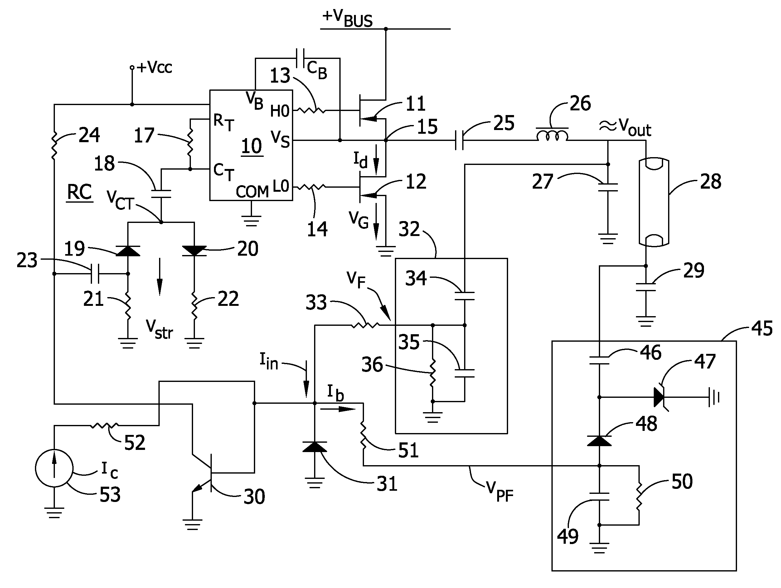
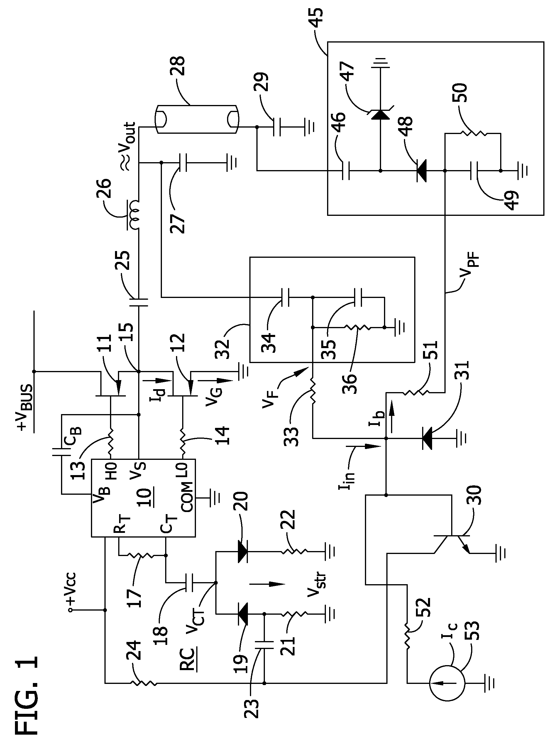
[0035]The present invention will be explained in more detail with reference to the attached drawings. FIG. 1 illustrates a ballast series resonance inverter circuit controlled by a standard self oscillating driver integrated circuit IC 10. The circuit of FIG. 1 employs a synchronizing control arrangement in combination with lamp current sense as feedback. The IC 10 drives half bridge power stages including power MOSFET transistors 11 and 12 controlled by HO and LO output pins of the IC 10 via gate resistors 13 and 14. The IC 10 is provided with a bootstrap capacitor CB with a first terminal connected to the pin VB of IC 10 which may be coupled to a bootstrap diode in the IC 10 (not shown). The second terminal of bootstrap capacitor CB is connected to a common junction 15 of transistors 11 and 12 connected in series to high voltage DC bus (+Vbus). The IC 10 is provided with RC-timing circuit comprising of a timing resistor 17 connected between pins RT and CT and a timing capacitor 18...


PUM


Abstract

A ballast having a rapid inverter frequency control circuit that is used for programmed operation during lamps starting, during normal operation of all lamps and during no lamp(s) operation. A method and circuit controls frequency shift via a combination of different feedback circuits. A control signal for the inverter controller is synthesized as a sum of phase shifted inverter output voltage feedback signal and lamp current sense signal indicating status of each lamp connected to the ballast output.

Description

FIELD OF THE INVENTION[0001]The present invention relates to electronic ballasts for powering gas discharge lamp(s) and, in particular, to programmed ballast series resonant inverters used for instant lamp starting.BACKGROUND OF THE INVENTION[0002]High frequency resonant inverters are typically used in electronic ballasts to power gas discharge lamps. One advantage of voltage fed resonant inverters with MOSFETs is high efficiency associated with Zero Voltage Switching (ZVS) and with low drain to source resistance of power MOSFETs when conducting. These inverters provide almost sinusoidal current to the gas discharge lamps that is very important for longer lamp life.[0003]A typical resonant inverter comprises a half bridge switching circuit with power MOSFETs generating high frequency AC to power a resonant load with at least one gas discharge lamp. Ballast voltage fed resonant inverter utilizes a series LC resonant tank circuit with the load connected in parallel to a resonant capac...

Claims


Application Information

Patent Timeline
Patent Type & Authority Patents(United States)
IPC IPC(8): H05B37/02
CPCH05B41/2827H05B41/2828Y02B20/186Y02B20/00
Inventor ALEXANDROV, FELIX I.
Owner OSRAM SYLVANIA INC
Why Eureka
Try Eureka