Radial bearing

a radial bearing and bearing seat technology, applied in the direction of sliding contact bearings, mechanical equipment, machines/engines, etc., can solve the problems of unsatisfactory both technically and financially, unsatisfactory fatigue strength of radial bearings, etc., to achieve high viscosity hydraulic means, reduce friction power loss, and reduce friction. the effect of the roller

Active Publication Date: 2009-12-08
SCHAEFFLER TECH AG & CO KG
View PDF18 Cites 11 Cited by
  • Summary
  • Abstract
  • Description
  • Claims
  • Application Information

AI Technical Summary

Benefits of technology

[0005]According to the invention, this objective is met in that the bearing seat features a width that varies over its extent in a direction of the longitudinal axis, such that the bearing seat, starting from the load zone, becomes significantly narrower outside of the load zone. A radial bearing embodied in this way optimally takes into consideration the circumstance that the bearing seat receiving a point load can become considerably narrower outside of the load zone and thus the potential of known bearings for reducing the rotationally moving mass, weight, processing expense, and costs can be used without negatively affecting the functional properties of the radial bearing. Such a negative effect would be produced when, due to the narrowing of the bearing seat, a critical bearing seat width is reached, below which a given fatigue strength of the radial bearing is no longer guaranteed. In the case of a radial bearing formed as a hydrodynamic sliding bearing, the decisive criteria for this negative effect can be a lubricant film that no longer bears weight or, in the case of a roller bearing, an impermissibly high loading of the bearing seat outside of the load zone.
[0014]Finally, in another construction of the invention, it can be advantageous that the width of the needle bearing generally corresponds to a maximum width of the variable width bearing seat allocated to the needle bearing, while a minimum width of the bearing seat is smaller than the length of the needles of the needle bearing. Simultaneously, for lubricating the needle bearing, only one unpressurized lubricant spray should be provided. With this construction of the invention, the lubricating conditions on the needle bearing can be improved in that the needles projecting locally and temporarily over the bearing seat can be exposed to the unpressurized lubricant spray to a greater degree. Conversely, this can also be beneficial for a discharge of abrasive particles from the track region of the needle bearing in favor of increased wear resistance of the radial bearing. In order to guarantee total contact of the length of the bearing seat with the needles in the region of the minimal width of this bearing seat, for this construction the use of a one-row needle bearing is to be preferred relative to the use of a multi-row needle bearing.

Problems solved by technology

However, for the required width outside of the load zone, this criteria still plays only a subordinate role, because here the bearing seat is subjected to a clearly lower mechanical load and, in individual cases, to no mechanical load at all.
This can produce significant disadvantages to the extent that the bearing seat, which is, for the most part, superior in terms of production, has a mass, which is undesired both technically and financially, and which is also avoidable, outside of the load zone.
Simultaneously, this leads to unnecessarily high processing costs for the bearing seat, which is to be machined with fine precision completely over its constant width, even outside of the load zone.
Such a negative effect would be produced when, due to the narrowing of the bearing seat, a critical bearing seat width is reached, below which a given fatigue strength of the radial bearing is no longer guaranteed.
In this case, a bearing seat of variable width can lead to a mass reduction of the housing, wherein a non-uniform mass distribution of the bearing seat over its extent does not require counterbalancing of the stationary housing.
Nevertheless, in comparison with conventional shafts with bearing seats of constant width, this opens up the possibility not only of increasing the unbalanced weight of the shaft for simultaneous mass reduction, but also makes possible a more extensive mass reduction of the shaft, in the case of a non-variable unbalanced weight, such that the original unbalanced weight increase is equalized by additional recesses, which reduce the mass and which are arranged on the unbalanced weight shaft on the side of the longitudinal axis relative to the center of mass.
Obviously, a fit can also be found between these two limiting cases for the unbalanced weight shaft, according to whether the design focus is on a moderate mass reduction with significant increase in unbalanced weight or on a clear mass reduction with unchanged increase in unbalanced weight.

Method used


Image

  • Radial bearing
  • Radial bearing
  • Radial bearing

Examples


Embodiment Construction

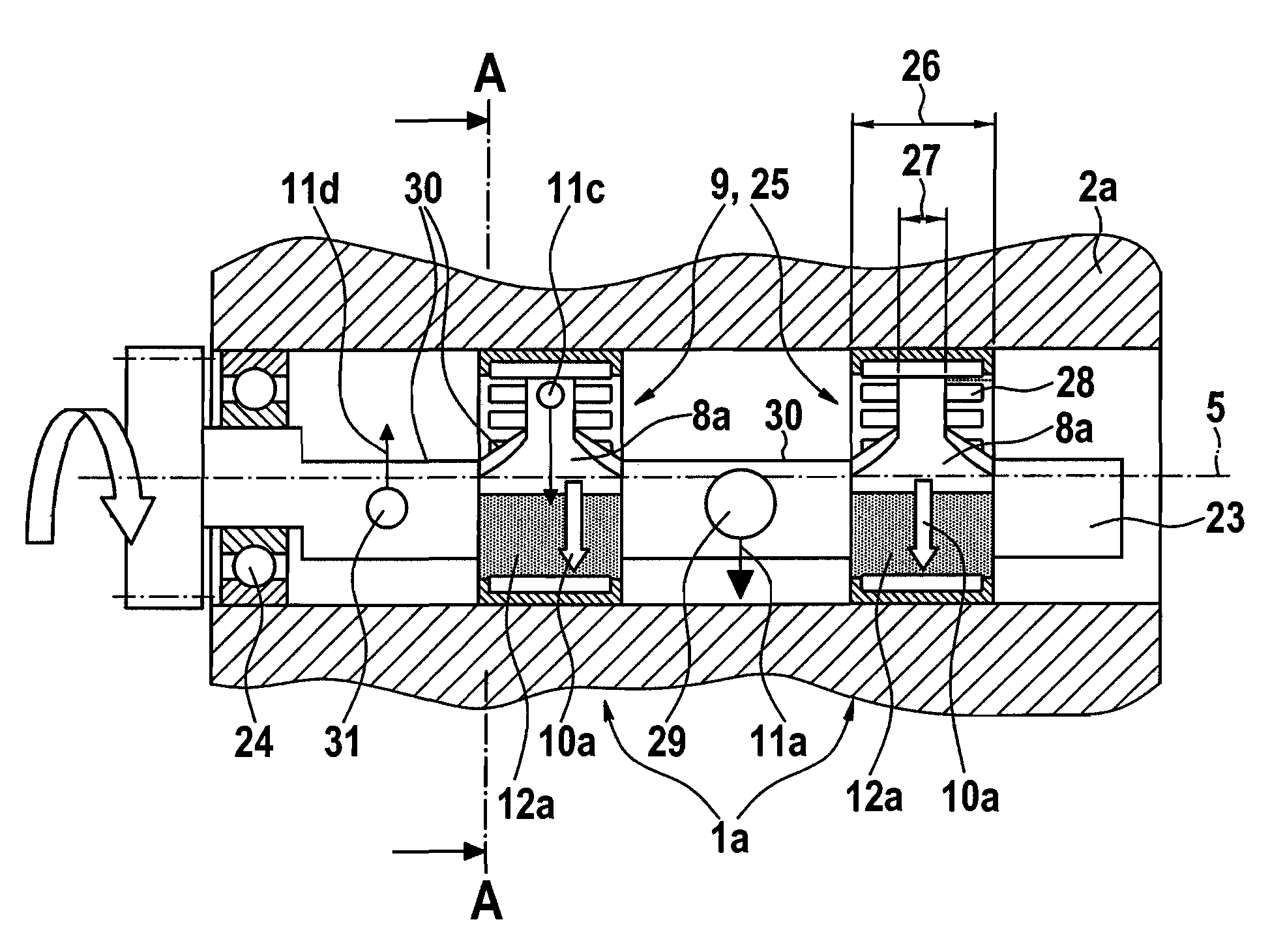
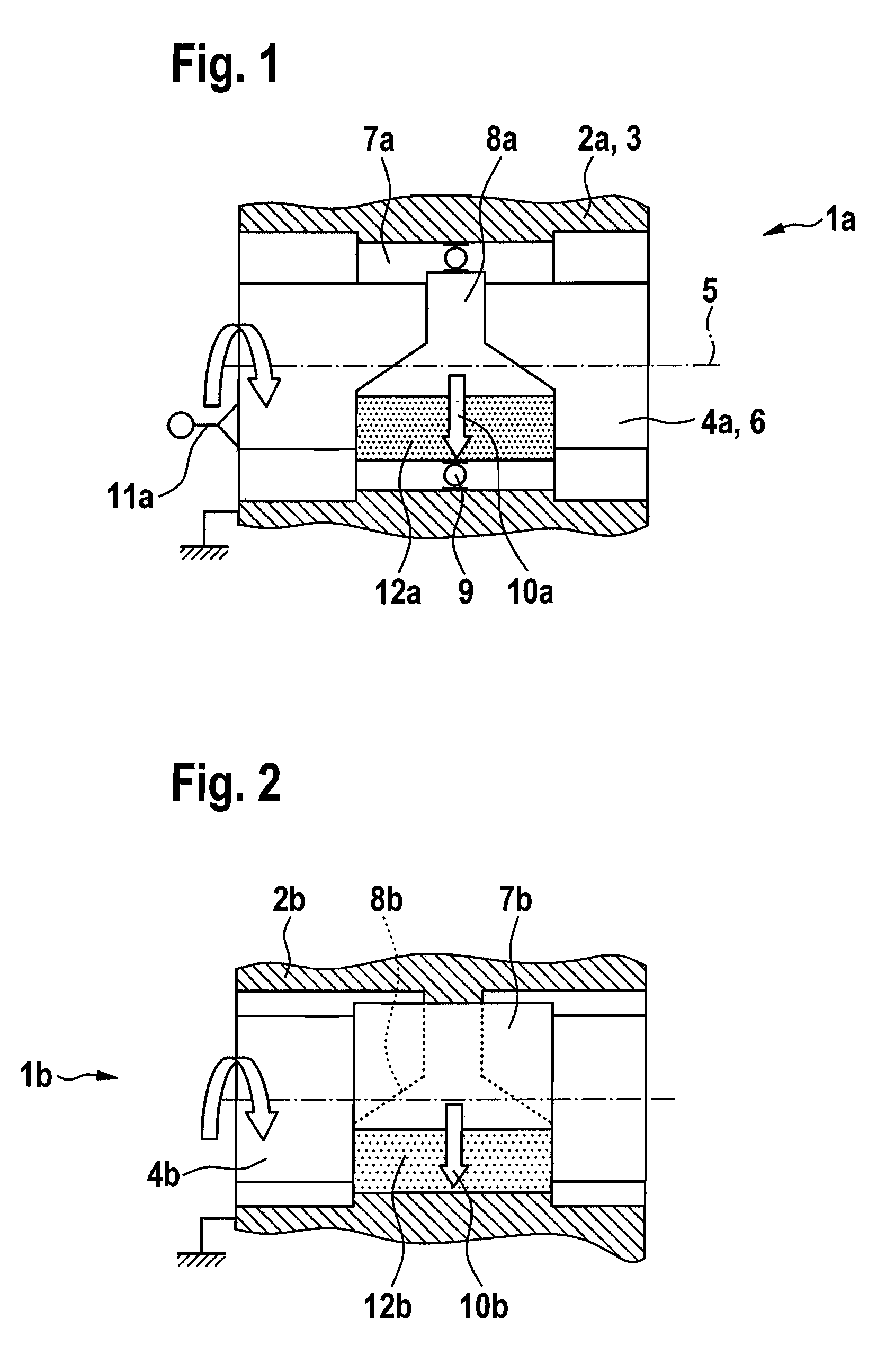
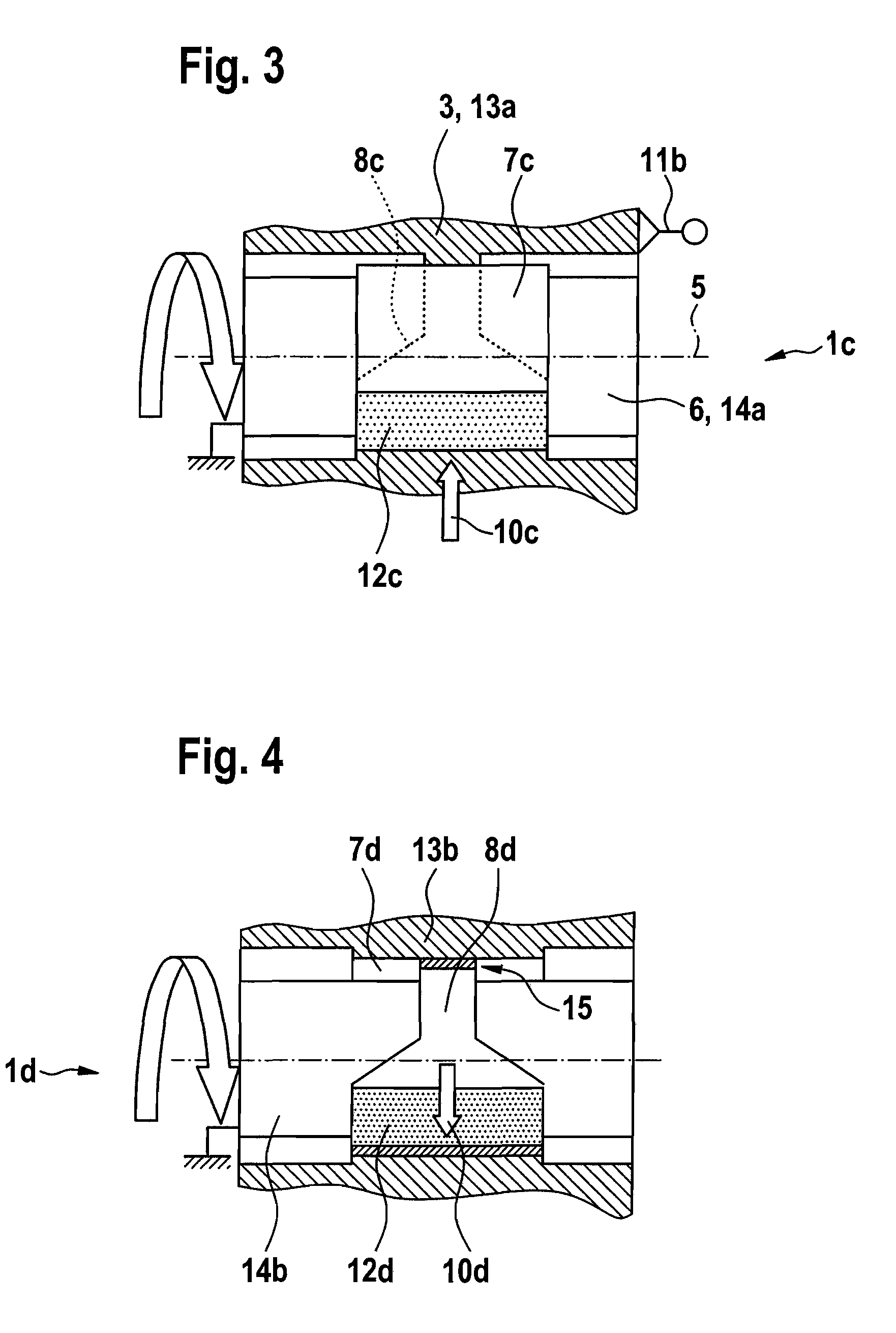
[0023]In FIG. 1, a radial bearing 1a according to the invention for a first load case is disclosed. Shown is an outer part 3, which is formed as a housing 2a and in which the inner part 6 formed as a shaft 4a and rotating about a longitudinal axis 5 is mounted radially. In the illustrated embodiment, a roller bearing 9 is located between a bearing seat 7a formed in the housing 2a and a bearing seat 8a formed on the shaft 4a, which can also be used as the radial bearing 1b, 1c, 1d according to FIGS. 2-4 as a bearing means. A radial load 10a rotating with the shaft 4a leads to a peripheral load on the bearing seat 7a of the housing 2a due to an unbalanced weight 11a arranged on the shaft 4a, while the radial load 10a is generally stationary relative to the bearing seat 8a of the shaft 4a and a load zone 12a (shown with shading) constructed on the shaft. While the bearing seat 7a of the housing 2a is constructed rotationally symmetric due to the peripheral load, the bearing seat 8a of ...


PUM


Abstract

A radial bearing (1a, 1b, 1c, 1d), especially a roller bearing (9) comprising an outer part (3) opposite an inner part (6), which rotate relative to each other about a common longitudinal axis (5) is provided, wherein the radial bearing (1a, 1b, 1c, 1d) includes a bearing seat (8a, 8b, 8c, 8d), which is formed in the outer part (3) or on the inner part (6) and which is generally stationary relative to a radial load (10a, 10b, 10c, 10d) acting on the bearing seat (8a, 8b, 8c, 8d) in a load zone (12a, 12b, 12c, 12d). The bearing seat (8a, 8b, 8c, 8d) features a variable width over its extent in a direction of the longitudinal axis (5), such that, starting from the load zone (12a, 12b, 12c, 12d), the bearing seat (8a, 8b, 8c, 8d) is significantly narrowed outside of the load zone (12a, 12b, 12c, 12d).

Description

FIELD OF THE INVENTION[0001]The invention relates to a radial bearing, especially a roller bearing, comprising an outer part opposite an inner part, wherein the outer part and the inner part rotate relative to each other about a common longitudinal axis, wherein the radial bearing comprises a bearing seat, which is formed in the outer part or on the inner part and which is generally stationary relative to a radial load acting on the bearing seat in a load zone.BACKGROUND OF THE INVENTION[0002]In principle, such a load case of the radial bearing is known in the state of the art and, in the case of the roller bearing, under the designation of the so-called point load, at which the radial load is generally stationary as a function of the movement relationships relative to the inner ring or the outer ring of the roller bearing. In contrast, the so-called peripheral load involves a load case, in which the radial load rotates relative to the inner ring or to the outer ring of the roller b...

Claims


Application Information

Patent Timeline
Patent Type & Authority Patents(United States)
IPC IPC(8): F02B75/06
CPCF16C17/02F16C19/06F16C33/585F16F15/267F16C33/581F16C19/46F16C2361/53F16C25/06F16C19/00F16C19/02
Inventor TISCH, SIEGFRIEDSOLFRANK, PETER
Owner SCHAEFFLER TECH AG & CO KG
Why Eureka
Try Eureka