
Golf club head

a golf club and head technology, applied in the field of golf club heads, can solve the problems of unsatisfactory shock absorption of the golf club head of the prior art, unsatisfactory gravity center of the golf club head, and relatively troublesome assembly of the counterweight unit to the golf club head with the use of screws, so as to improve the bonding strength of the counterweight unit and facilitate assembly. , the effect of flexible adjustment of the weight distribution

Inactive Publication Date: 2009-12-08
ADVANCED INT MULTITECH CO LTD
View PDF21 Cites 92 Cited by
  • Summary
  • Abstract
  • Description
  • Claims
  • Application Information

AI Technical Summary

Benefits of technology

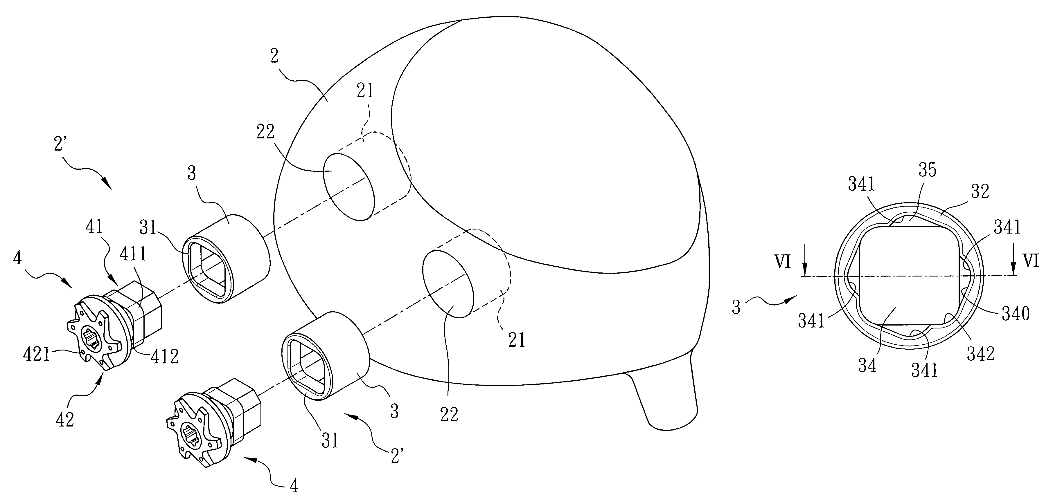
The present invention provides a golf club head that is easy to assemble, has improved bonding strength of a counterweight unit, and is flexible in adjusting its weight distribution. The golf club head includes a head body with a cavity and a counterweight unit fitted in the cavity. The counterweight unit has a sleeve body with first and second cavities and inner walls with first and second corners. The sleeve body also has a shoulder face formed at the junction of the first and second cavities. The insert body includes an insert portion removably inserted into the sleeve body and an abutting portion extending outward from the sleeve body and abutting against the first end face. The insert portion has at least one flange that engages the second corner and that has a stop face abutting against the shoulder face.

Problems solved by technology

Since the counterweight unit is bonded to the golf club head by welding, the gravity center of the golf club head is not adjustable according to the specific striking requirements of the golfer.
Furthermore, the shock absorption of the golf club heads of the prior art is unsatisfactory.
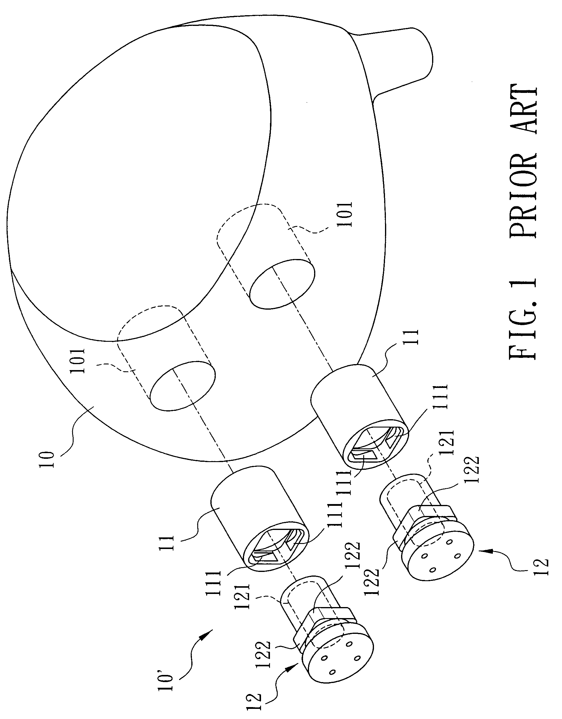
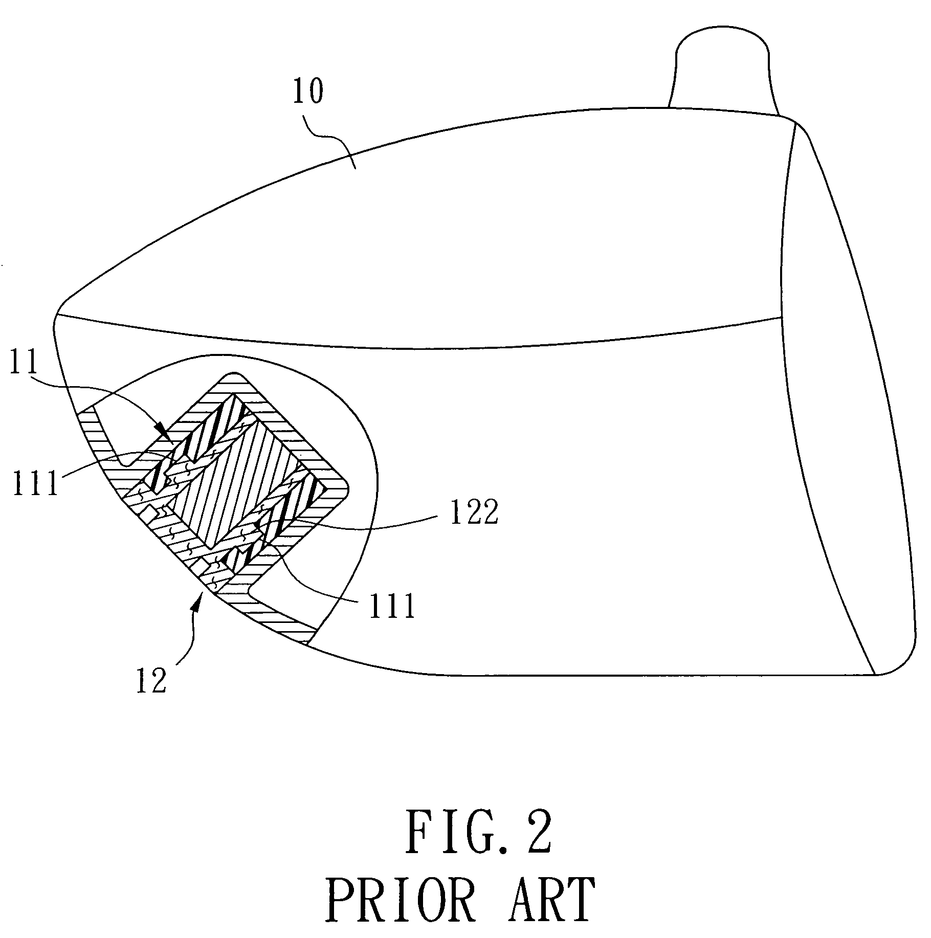
However, assembly of the counterweight unit to the golf club head with the use of screws is relatively troublesome.
The stability of the golf club head is unsatisfactory, and the insert body 12 is liable to separate from the sleeve body 11 when a golf ball is struck.

Method used


Image

  • Golf club head
  • Golf club head
  • Golf club head

Examples


Embodiment Construction

[0029]Before the present invention is described in greater detail, it should be noted that like elements are denoted by the same reference numerals throughout the disclosure.

[0030]Referring to FIG. 3, the first preferred embodiment of a golf club head according to this invention is shown to include a head body 2 and two counterweight units 2′.

[0031]The head body 2 is formed with two cavities 21 provided at the back of the head body 2 and spaced apart from each other. Each of the cavities 21 has an opening 22 at an outer surface of the head body 2. The head body 2 is made of titanium alloy, stainless steel, carbon steel, or the like.

[0032]Each of the counterweight units 2′ is fitted in a corresponding one of the cavities 21, and includes a sleeve body 3 and an insert body 4.

[0033]Referring to FIGS. 4, 5, and 6, the sleeve body 3 is made of plastic, rubber, metal, or the like, and has a first end face 31, a second end face 32 opposite to the first end face 31 and extending to the dept...


PUM


Abstract

A golf club head includes a head body formed with a cavity, and a counterweight unit fitted in the cavity and including a sleeve body and an insert body. The sleeve body has a first end face, a second end face, first and second cavities, and first and second inner walls. The first inner wall has at least one first corner. The second inner wall has at least one second corner out of alignment with the first corner. The sleeve body further has at least one shoulder face formed at a junction of the first and second cavities. The insert body includes an insert portion removably inserted into the sleeve body, and an abutting portion extending outward from the sleeve body and abutting against the first end face. The insert portion has at least one flange engaging the second corner and having a stop face abutting against the shoulder face.

Description

CROSS-REFERENCE TO RELATED APPLICATION[0001]This application claims priority of Taiwanese Application No. 096219586, filed on Nov. 20, 2007.BACKGROUND OF THE INVENTION[0002]1. Field of the Invention[0003]The invention relates to a golf club head, more particularly to a golf club head having an improved weight distribution design.[0004]2. Description of the Related Art[0005]When choosing a golf club head, the factors to be considered primarily include controllability and stability. Therefore, the golf player should choose a golf club head having a good weight distribution design so as to increase the controllability and stability. Conventionally, the method for the weight distribution design of the golf club head includes providing a counterweight unit that is usually assembled to the golf club head by welding or through screws.[0006]In Taiwanese Patent Nos. I224017 and I227675, a counterweight unit is bonded to a golf club head by welding so as to lower a gravity center of the golf ...

Claims


Application Information

Patent Timeline
Patent Type & Authority Patents(United States)
IPC IPC(8): A63B53/06E01B9/12A63B53/04A63B102/32
CPCA63B53/0466A63B59/0092A63B2053/0433A63B2209/00A63B2209/02A63B2053/0491A63B60/54A63B53/0433A63B60/02
Inventor AKINORI, SASAMOTOLEEHOU, YUAN-JENHSIAO, TE-FU
Owner ADVANCED INT MULTITECH CO LTD
Learn More