Mixed resolution displays

a display and resolution technology, applied in the field of mixed resolution displays, can solve the problems of users' visual switching back, technology not reaching the mass, and bottlenecks of computer systems, and achieve the effects of reducing the visible gap between the two display units, reducing the size of image elements, and minimizing spa

Inactive Publication Date: 2009-12-08
XEROX CORP
View PDF34 Cites 67 Cited by
  • Summary
  • Abstract
  • Description
  • Claims
  • Application Information

AI Technical Summary

Benefits of technology

[0028]Two or more display units with different resolutions are combined such that the geometry of images displayed across the multiple display units is preserved and the image appears to be substantially continuous to a viewer of the image. Compatibility of the sizes of image elements on different display units is achieved by using display unit-specific scaling to compensate for the different pixel sizes on the individual display units. Several embodiments for combining multiple display units, at least two of which use differently sized pixels, into a mixed resolution display are described. One embodiment combines a flat high-resolution display, such as an LCD, with a projection display, such that the display area of the high-resolution display is surrounded by the display area of the projection display. The visible gap between the two display units is minimized, while using minimal space and a cost-efficient setup.

Problems solved by technology

For many tasks involving visual representations, the display thereby has become the bottleneck of computer systems.
Current technology is able to provide large high-resolution displays, but technologies proposed so far for such displays are still cost-intensive, space-intensive, or both, which has prevented these technologies from reaching the mass market.(c) They can use an appropriate visualization technique that allows fitting the required data into a small screen by reducing the space allocated for irrelevant information.
The drawback of this approach is that it requires users to visually switch back and forth between the two distinct views and to reorient themselves every time they switch.
However, the downside of this approach is that it introduces distortion, which makes some content, for example photographic content, difficult to recognize.
Both of these visualization techniques use different scaling for the different display regions, making it difficult to visually compare sizes and lengths between objects located in different regions.
However this implementation, does not offer the size preservation described above.
Multiple monitor configurations to extend the user's display space have not always been able to maintain this parameter.
The lag resulting from the tracking mechanism inserts an undesirable time-discontinuity.

Method used


Image

  • Mixed resolution displays
  • Mixed resolution displays
  • Mixed resolution displays

Examples


embodiment 1

VNC Implementation

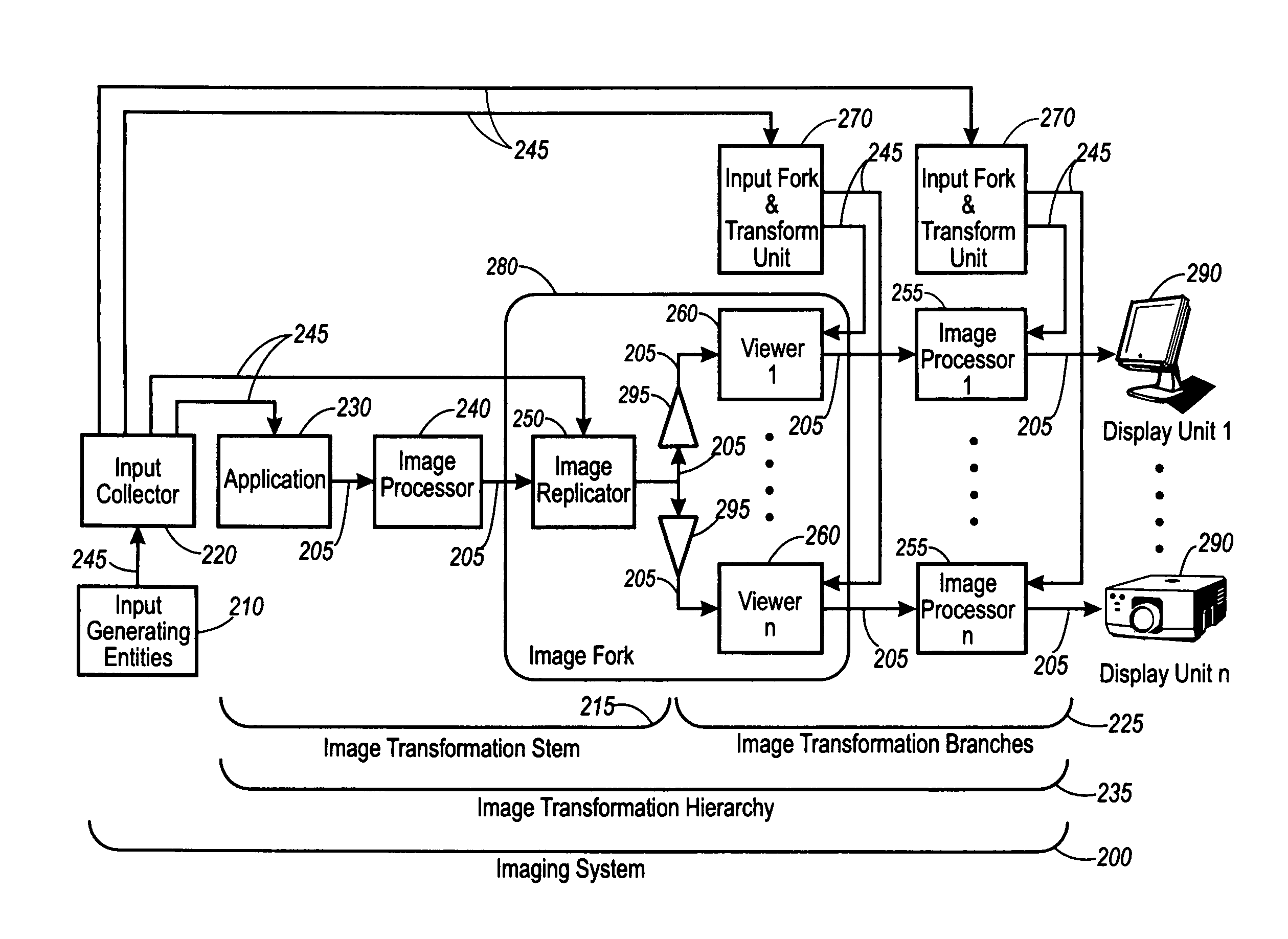
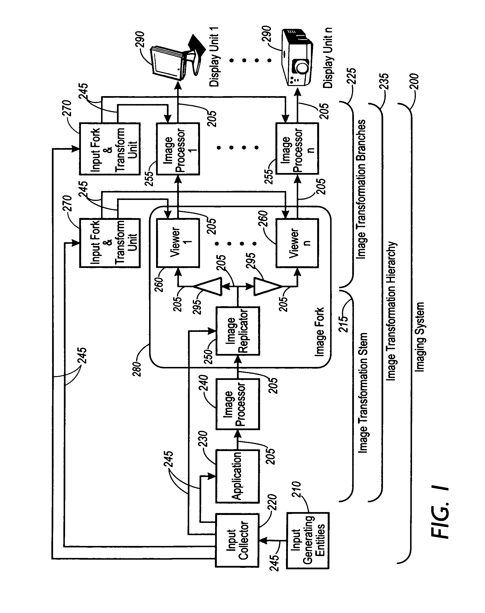
[0072]FIG. 4 shows one embodiment of the imaging system 200 implemented with several computer systems linked together over a network. As this embodiment refers to the same components shown in FIG. 1, the same reference numerals will be used to denote similar components. The displays 290 were implemented using a projection system and a LCD screen. The Virtual Network Computing (VNC) software, available from AT&T under the GNU public license, was used to implement a large portion of the image system 200. In essence, the VNC software is a remote display system that allows a user to view a computing ‘desktop’ environment not only on the machine where it is running, but from anywhere on the Internet and from a wide variety of machine architectures. The VNC server program was run on a computer system running the Linux operating system (Linux computer) and implemented a portion of the input collector 220, application 230, image processor 240, and the image replicator 250....

embodiment 2

Unreal Tournament Implementation

[0077]FIG. 5 shows an embodiment where the imaging system 200 can also be used to implement a 3D game scenario, again using two computer systems linked across a network sharing the same view of a single application. As before, the views must be scaled differently to maintain visual continuity across the focus plus context display. In this implementation, the Unreal Tournament software by Epic Games was used and installed on two separate computer systems both running Microsoft Windows (Microsoft computer 1 and Microsoft computer 2). Microsoft computer 1 and Microsoft computer 2 were connected to each other via a networked setting. The Unreal Tournament software on Microsoft computer 1 was utilized as the input collector 220 and the image transformation stem 215. The data was then shared with both computers such that the Unreal Tournament software on Microsoft computer 1 implemented one of the image transformation branches 225 while Unreal Tournament so...

embodiment 3

ACDsee

[0080]FIG. 6 shows a diagram of an embodiment used to view previously constructed graphical data. Therefore, it can be viewed that the initial input to the system performed by the input generating entities 210, input collector 220, application 230, image processor 240, and image replicator 250 contained in subsystem 215 were all performed offline to generate the initial image data. This was done using Photoshop, available from Adobe Systems, running on a standard computer set-up, to generate and save two images files. Although, in this implementation Photoshop was used to generate the image files, this is used for exemplary purposes only and any image files in any format could have been used.

[0081]In this embodiment, the remainder of the imaging system 200 was implemented using three computers utilizing an asynchronous setup. Two of the computers were set up to run ACDsee image viewer software available from ACD systems and Microsoft Windows (Microsoft computer 1 and Microsoft...


PUM


Abstract

Two or more display units with different resolutions are combined such that the geometry of images displayed across the multiple display units is preserved and the image appears to be substantially continuous to a viewer of the image. Compatibility of the sizes of image elements on different display units is achieved by using display unit-specific scaling to compensate for the different pixel sizes on the individual display units.

Description

[0001]This patent application claims priority benefit from US Provisional Application No. 60 / 290,493 filed May 11, 2001.REFERENCE TO RELATED APPLICATIONS[0002]This patent application is related to copending U.S. patent application Ser. No. 10 / 015,642 titled “Methods of Using Mixed Resolution Displays”, by Baudisch et al., U.S. patent application Ser. No. 10 / 015,680 titled “System Utilizing Mixed Resolution Displays”, by Baudisch et al. and U.S. patent application Ser. No. 10 / 015,677 titled “Methods of Using Mixed Resolution Displays”, by Baudisch et al. all filed concurrently herewith.INCORPORATION BY REFERENCE[0003]The following patents and / or patent applications are herein incorporated by reference:[0004]U.S. Pat. No. 6,018,340, titled “Robust Display Management in a Multiple Monitor Environment”, by Butler et al. and issued on Jan. 25, 2000,[0005]U.S. Pat. No. 5,949,430, titled “Peripheral Lenses for Simulating Peripheral Vision on a Display Device”, by Robertson et al. and issue...

Claims


Application Information

Patent Timeline
Patent Type & Authority Patents(United States)
IPC IPC(8): G09G5/00G06F3/14G09G3/00H04N9/12
CPCG06F3/1438G06F3/1446H04N9/12G09G2320/0693G09G2340/0407G09G3/006
Inventor BAUDISCH, PATRICK
Owner XEROX CORP
Why Eureka
Try Eureka