Thermal break and panel joint for an air handling enclosure

a technology of panel joints and air handling enclosures, which is applied in the direction of transportation and packaging, heating types, lighting and heating apparatus, etc., can solve the problems of localized heat loss that may still occur at the uninsulated metal-to-metal joint, inconsequential system overall efficiency, and condensation on the join

Active Publication Date: 2009-05-05
TRANE INT INC
View PDF46 Cites 23 Cited by
  • Summary
  • Abstract
  • Description
  • Claims
  • Application Information

AI Technical Summary

Benefits of technology

[0011]Another object of some embodiments is to provide a thermal break for a joint that connects two panels end-to-end in direct contact with each other (i.e., in metal-to-metal contact with the exception of an inconsequential layer of paint or some other relatively thin coating).
[0012]Another object of some embodiments is to provide a panel with an edge that lies at a slight acute angle to the face of the panel so that when the edge abuts a similar edge of an adjoining panel, the two panels close any visible gap that might otherwise exist.
[0015]Another object of some embodiments is to connect two panels with a tongue-and-groove joint, wherein the tongue and groove are formed as an integral extension of the panel sheets that provide the outer faces of each panel, thereby minimizing the number of parts and maximizing the panels' strength.

Problems solved by technology

Although such insulation can improve the operating efficiency of the air handling system, some localized heat loss may still occur at the uninsulated metal-to-metal joint where two panels come together.
Such localized heat loss may be inconsequential to the system's overall efficiency; however, when there is a significant temperature differential between the interior and exterior of the enclosure, condensation may form on the joint.
The condensation can lead to poor air quality, water damage or create a wet, slippery floor around the enclosure.
In some cases, the condensation may freeze, and the accumulating frost can provide a poor appearance or prevent doors or other moving parts of the enclosure from operating.
These seals, however, are visible and may be exposed to sunlight whose ultraviolet radiation may hasten their deterioration.
Moreover, some consider exposed seals unsightly.
U.S. Pat. No. 6,374,571 shows how a panel with a hidden seal can be attached to a frame member, but then, of course, the enclosure requires a frame, which adds cost to the enclosure.

Method used


Image

  • Thermal break and panel joint for an air handling enclosure
  • Thermal break and panel joint for an air handling enclosure
  • Thermal break and panel joint for an air handling enclosure

Examples


Embodiment Construction

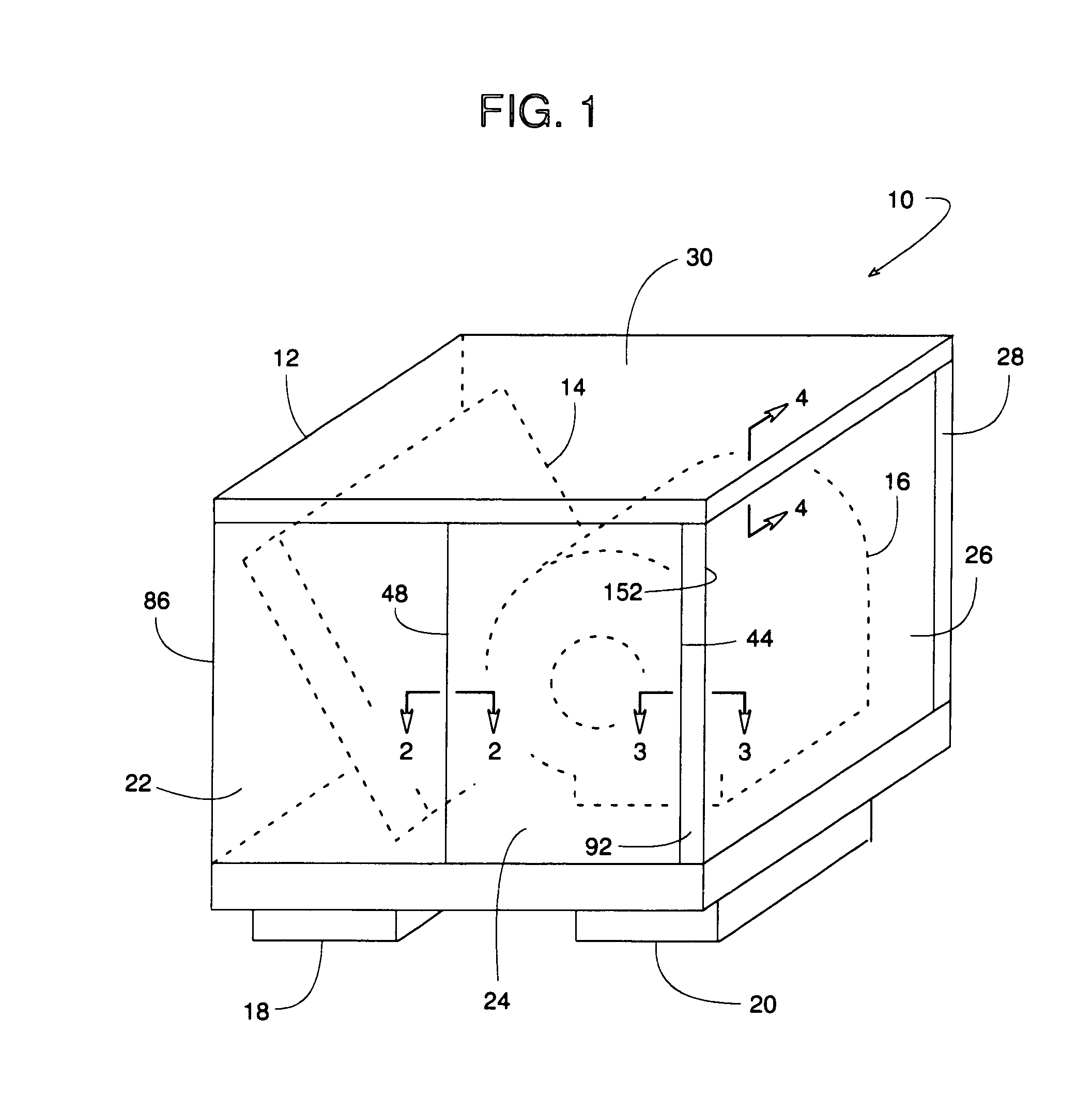
[0022]FIG. 1 shows an air handler 10 comprising an enclosure 12 that contains a heat exchanger 14, a blower 16, compressor, filter, or some other type of HVAC equipment. Enclosure 12 is open to an inlet 18 and an outlet 20 for conveying air across the equipment housed within the enclosure. The equipment inside enclosure 12 is used in some manner to handle or condition air associated with an HVAC system. Since a temperature differential usually exists between the enclosure's interior and exterior, enclosure 12 is preferably insulated.

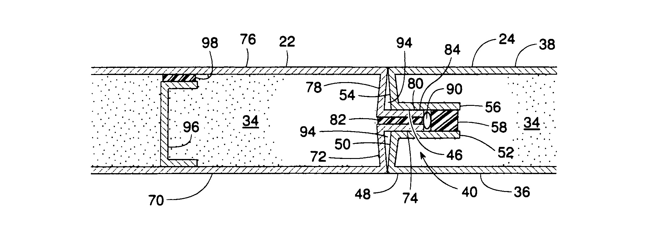
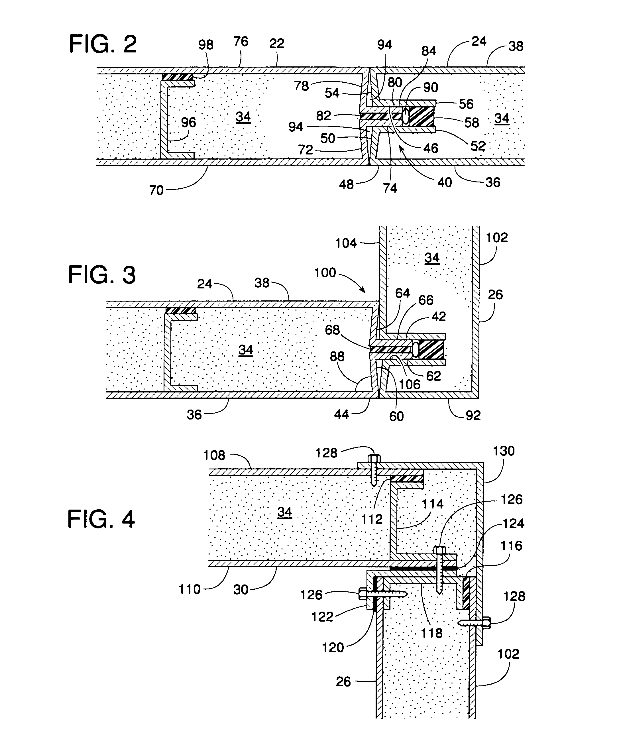
[0023]Enclosure 12 can be made of any number of insulated panel assemblies 22, 24,26, 28, and 30 that have a thermal insulating core sandwiched between inner and outer panel sheets. The inner and outer panel sheets are held together with double-sided tape. The tape also provides a thermal break where adjoining panel assemblies come together at a tongue-and-groove joint. Details of some embodiments of assemblies 22, 24, 26, 28, and 30 are shown in FIGS. 2...


PUM


Abstract

An HVAC air handling enclosure is comprised of individual panel assemblies each of which are fabricated from two panels or skins that are held together by double-sided adhesive tape. Adjacent panel assemblies are connected by a metal tongue-and-groove joint that relies on that same tape as a thermal break at the joint. After assembly, the thermal break and the tongue and groove elements of the joint are completely hidden from view. Moreover, the joint includes an internal cavity that can take up surplus sealant that may ooze out from within the tongue-and-groove joint during assembly, whereby the surplus sealant also remains hidden.

Description

BACKGROUND OF THE INVENTION[0001]1. Field of the Invention[0002]The subject invention generally pertains to HVAC air handling enclosures and more specifically to a thermal break and panel joint for such an enclosure.[0003]2. Description of Related Art[0004]Heat exchangers, compressors, blowers, filters and other HVAC equipment are often housed within an air handling enclosure. The enclosure helps shelter the equipment, provides a sound barrier, and perhaps most importantly, the enclosure provides a conduit for directing the air through the equipment. Air handling enclosures usually comprise a number of sheet metal panels that are interconnected to create a box-like structure.[0005]In many cases, the panels are insulated to minimize heat loss between the interior and exterior of the enclosure. Although such insulation can improve the operating efficiency of the air handling system, some localized heat loss may still occur at the uninsulated metal-to-metal joint where two panels come ...

Claims


Application Information

Patent Timeline
Patent Type & Authority Patents(United States)
IPC IPC(8): E04C2/00E04B2/00
CPCF24F3/0442F24F13/20F24F2013/221F24F2221/36
Inventor KANDASAMY, GANESON
Owner TRANE INT INC
Why Eureka
Try Eureka