Portable wireless device

a wireless device and portability technology, applied in the direction of flexible/turnable line connectors, substation equipment, resonance antennas, etc., can solve the problems of reducing the quality of phone conversations, and the conventional method has thus encountered a difficult problem of reducing sar, etc., to achieve a wide range of bandwidth, high radiation efficiency, and the effect of reducing the specific absorption ra

Inactive Publication Date: 2009-12-08
PANASONIC CORP
View PDF14 Cites 12 Cited by
  • Summary
  • Abstract
  • Description
  • Claims
  • Application Information

AI Technical Summary

Benefits of technology

[0009]a hinged section for coupling a first housing to a second housing and allowing these housings to be folded and unfolded;
[0017]The foregoing structure allows the portable wireless device to obtain high radiation efficiency with the upper housing and the lower housing unfolded for carrying out a phone conversation. The peak of antenna current existing in the wiring bundle (flexible cable) close to the temporal region of a human body can be dispersed. The Specific Absorption Rate (SAR) can be thus lowered, and a bandwidth can be widened by compound resonance.
[0018]The portable wireless device of the present invention thus disperses the peak of antenna current existing in the flexible cable close to the temporal region of a human body during a phone conversation, so that the SAR can be lowered.

Problems solved by technology

Reduction of the SAR needs to reduce the electric power of radio wave radiated from the wireless device; however, the reduction of the power lowers the quality of a phone conversation.
The conventional method has thus encountered a difficult problem of reducing the SAR.

Method used


Image

  • Portable wireless device
  • Portable wireless device
  • Portable wireless device

Examples


exemplary embodiment 1

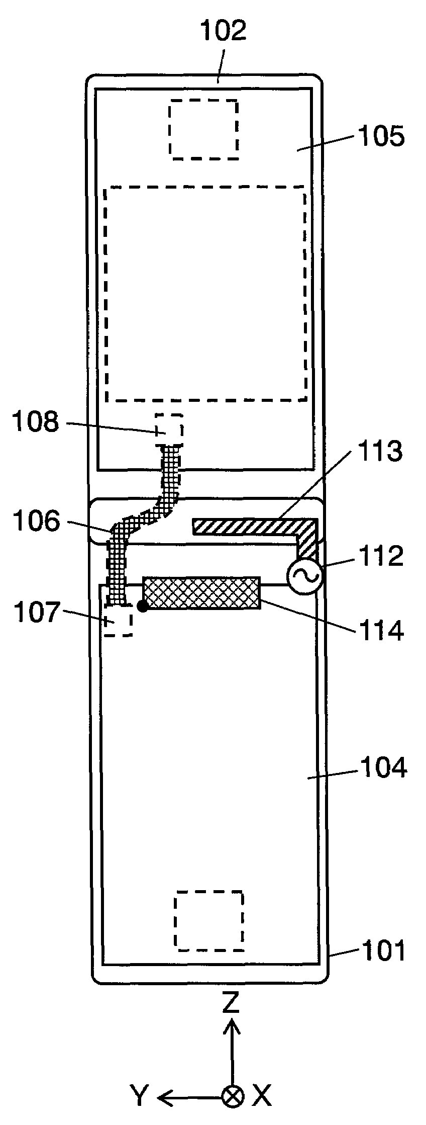
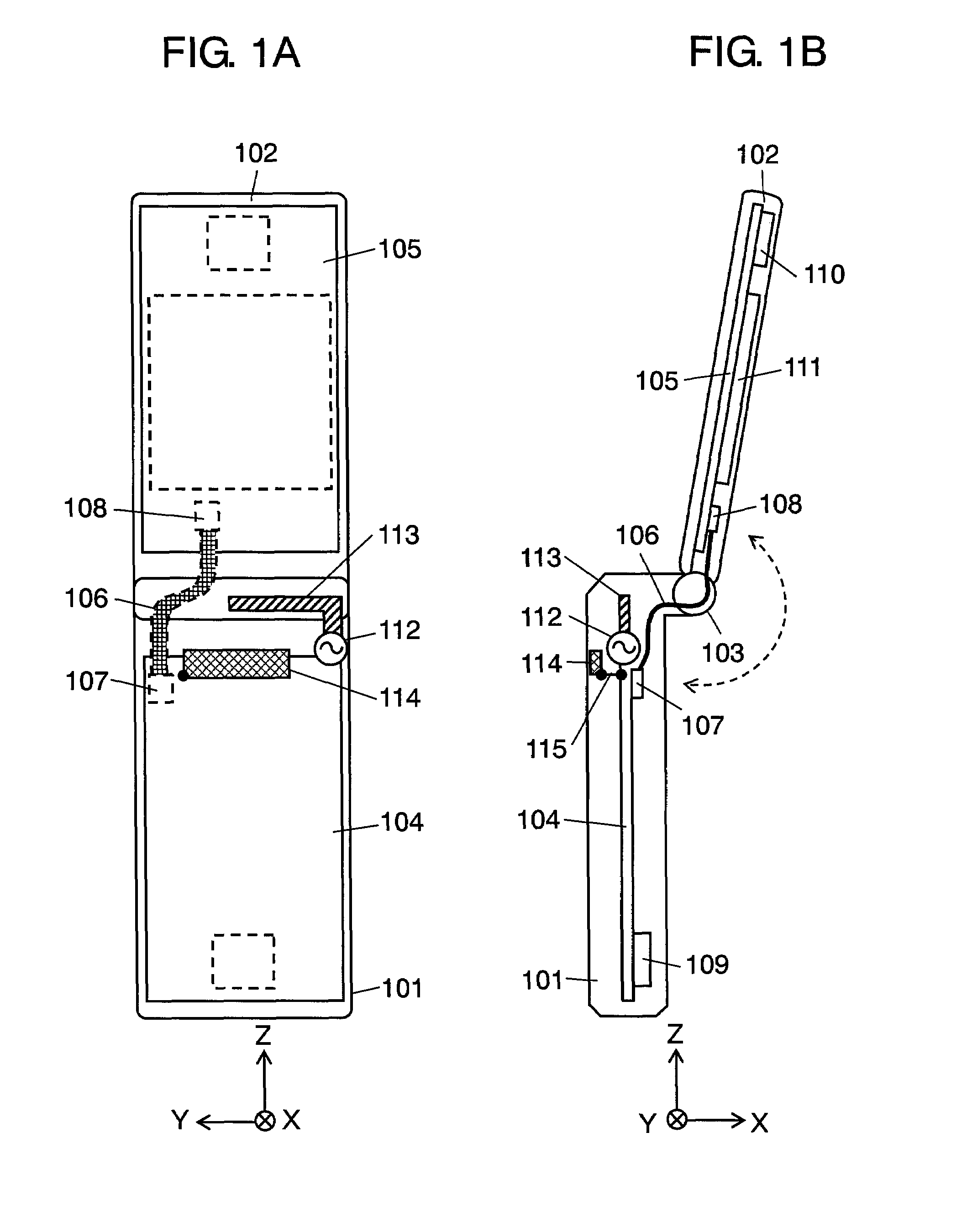
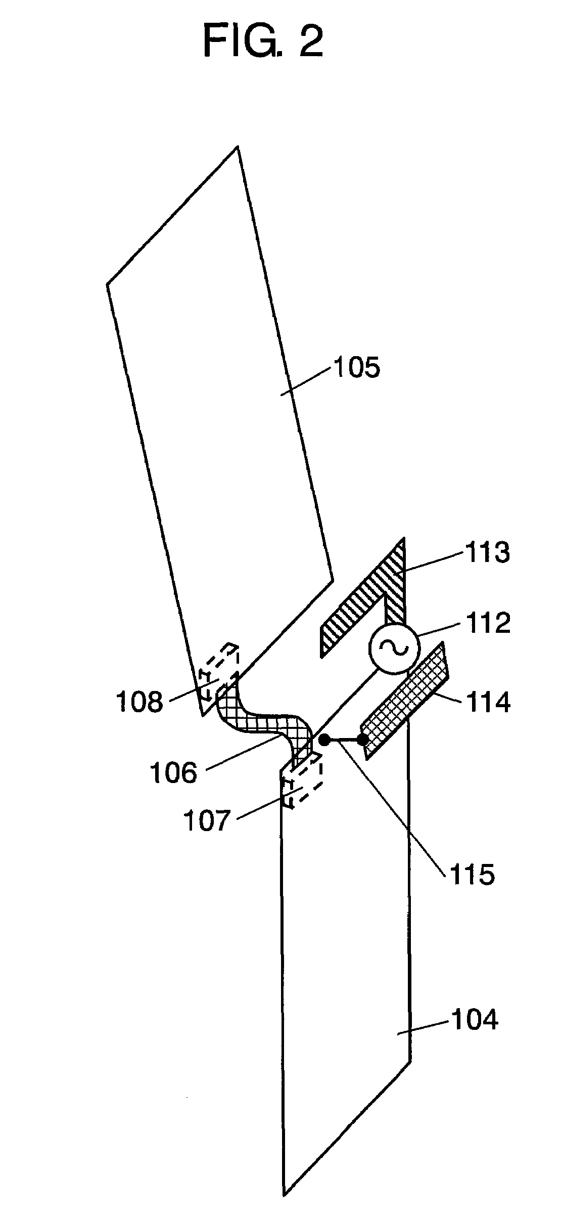
[0040]FIG. 1A shows a rear view of a portable wireless device in accordance with the first embodiment of the present invention. FIG. 1B shows a lateral view of the portable wireless device in accordance with the first embodiment of the present invention. FIG. 3 shows a perspective view illustrating a main portion of another portable phone in accordance with the first embodiment of the present invention. FIG. 4 schematically illustrates the portable phone, in accordance with the first embodiment, during the progress of a phone call.

[0041]In FIGS. 1 and 2, the portable phone in accordance with the first embodiment includes a foldable mechanism which couples lower housing 101 to upper housing 102 with hinged section 103. Lower housing 101 accommodates antenna element 113, power feeder 112 and lower circuit board 104. Antenna element 13 has a length of approx. a quarter of wavelength of the frequency presently used. Antenna element 13 is bent and shapes like letter “L”. Power feeder 12 ...


PUM


Abstract

A portable wireless device is formed of a lower housing and an upper housing coupled together by a hinged section, which makes the device foldable. A lower circuit board is coupled to an upper circuit board by a flexible cable, which is placed away from a power feeder of an antenna element with a given space and near the hinged section along the width direction of this foldable device. An end of conductive element is shorted to the lower circuit board with a shorting conductor near a connector which couples the flexible cable to the lower circuit board. The foregoing structure allows the portable and foldable wireless device to reduce an amount of energy supposed to be absorbed into a temporal region of a human body while the electric power of the transmitted radio wave is maintained during a phone conversation.

Description

[0001]This application is a national phase application of PCT International Application No. PCT / JP2006 / 312961.TECHNICAL FIELD[0002]The present invention relates to a portable wireless device of which upper housing is coupled in a foldable / unfoldable manner to its lower housing by a hinged section.BACKGROUND ART[0003]Portable phones have been widely accepted in the market, and various types of portable phones have been developed. Among these types, a compact and double-backed type is widely used. When the phone is not used, this double-backed type can be folded (double-backed) to be more compact.[0004]The law effective since Jun. 2002 regulates the average amount of energy of radio wave transmitted from wireless devices such as a portable phone while a phone call is in progress. The law defines the average amount of energy (Specific Absorption Rate, hereinafter referred to as SAR) absorbed for six minutes into a specific portion (particularly to temporal region) of human body. It is ...

Claims


Application Information

Patent Timeline
Patent Type & Authority Patents(United States)
IPC IPC(8): H04M1/00H01Q1/24H04B1/38H04B1/3822H04M1/02
CPCH01Q1/243H04B1/3838H04M1/0214H01R35/02H01R2201/16
Inventor UEJIMA, HIROYUKIIMANO, DAIGOYAMAGUCHI, TAKESHI
Owner PANASONIC CORP
Why Eureka
Try Eureka