Orbital engine/pump with multiple toroidal cylinders

a technology of toroidal cylinders and orbital engines, which is applied in the direction of rotary piston engines, propellers, portable lifting, etc., can solve the problems of excessive torque output, excessive pulsing, and relatively complicated arrangement of the control of the vanes movement of the art vane engine, so as to reduce the variation of output

Inactive Publication Date: 2009-12-15
AROV ANATOLY
View PDF19 Cites 18 Cited by
  • Summary
  • Abstract
  • Description
  • Claims
  • Application Information

AI Technical Summary

Benefits of technology

[0013]According to an aspect of the invention includes at least two combustion units interconnected by a common drive train such that vane positions in respective toroidal cylinders are maintained in synchronization with each other, and wherein each unit has four working chambers defined by rotating vanes which accelerate towards and away form adjacent vanes as the impellers rotate in the toroidal cylinder. The impellers of each unit are driven by corresponding gears of common gear train which controls the vane movement as a function of the position in said cylinder. The units cooperate with each other by being out of phase in a manner to reduce output variation.

Problems solved by technology

These prior art vane engines have relatively complicated arrangements for controlling of the vanes movement and have not proved entirely satisfactory.
First of the difficulties with my prior engine or pump was excessive pulsing of torque output for engine or excessive pulsing of media flow for pump with only two working chambers in one toroidal cylinder.
Second of the difficulties with my prior engine is the lack of a simple porting arrangement for media flow between the “cylinders” and housing inlet / outlet holes, compression and / or supplying a suitable air fuel mixture for combustion and valving for exhausting combustion products.
Another difficulty is multiplication of engine power or pump flow increase.

Method used


Image

  • Orbital engine/pump with multiple toroidal cylinders
  • Orbital engine/pump with multiple toroidal cylinders
  • Orbital engine/pump with multiple toroidal cylinders

Examples


Embodiment Construction

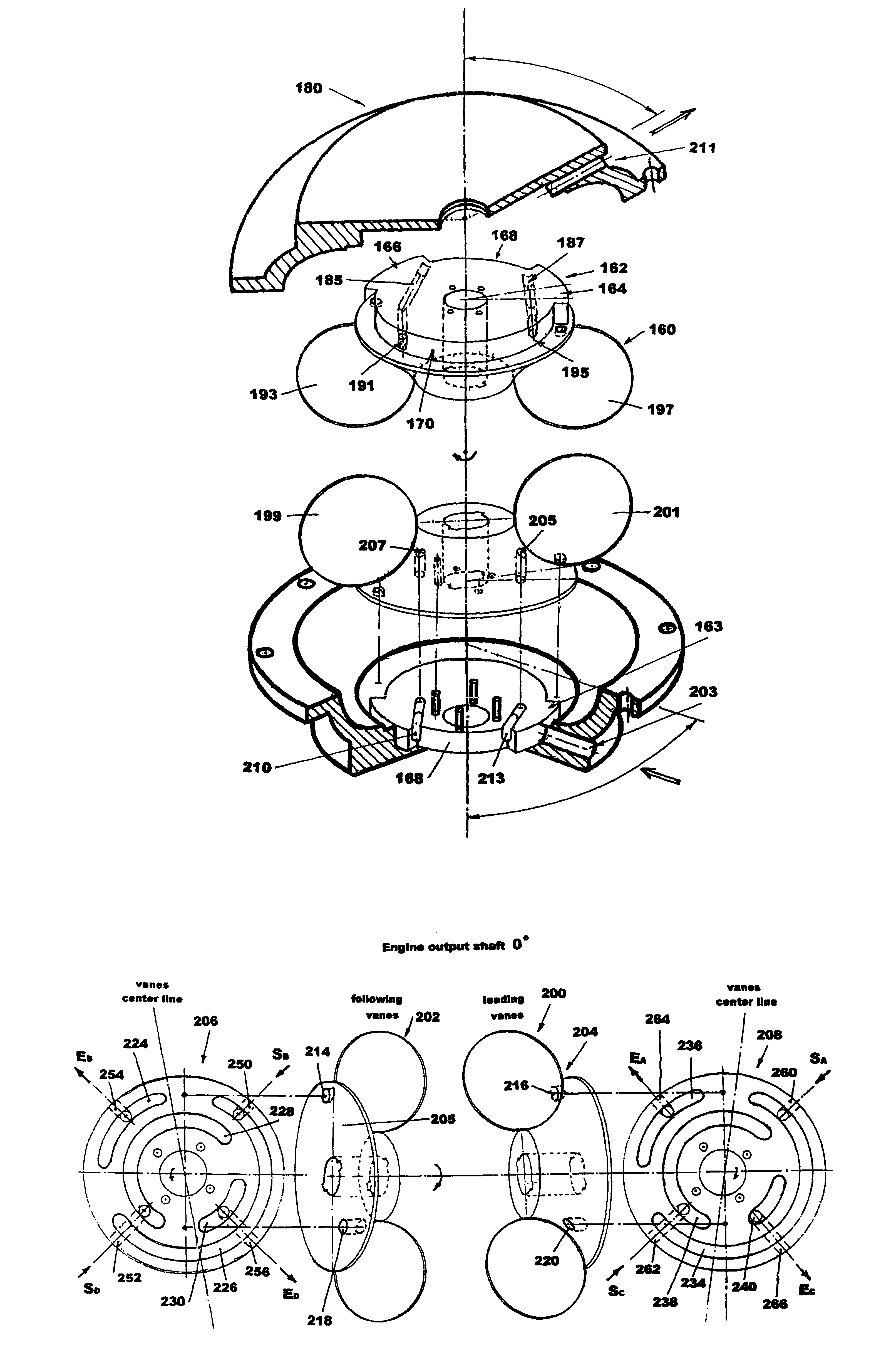
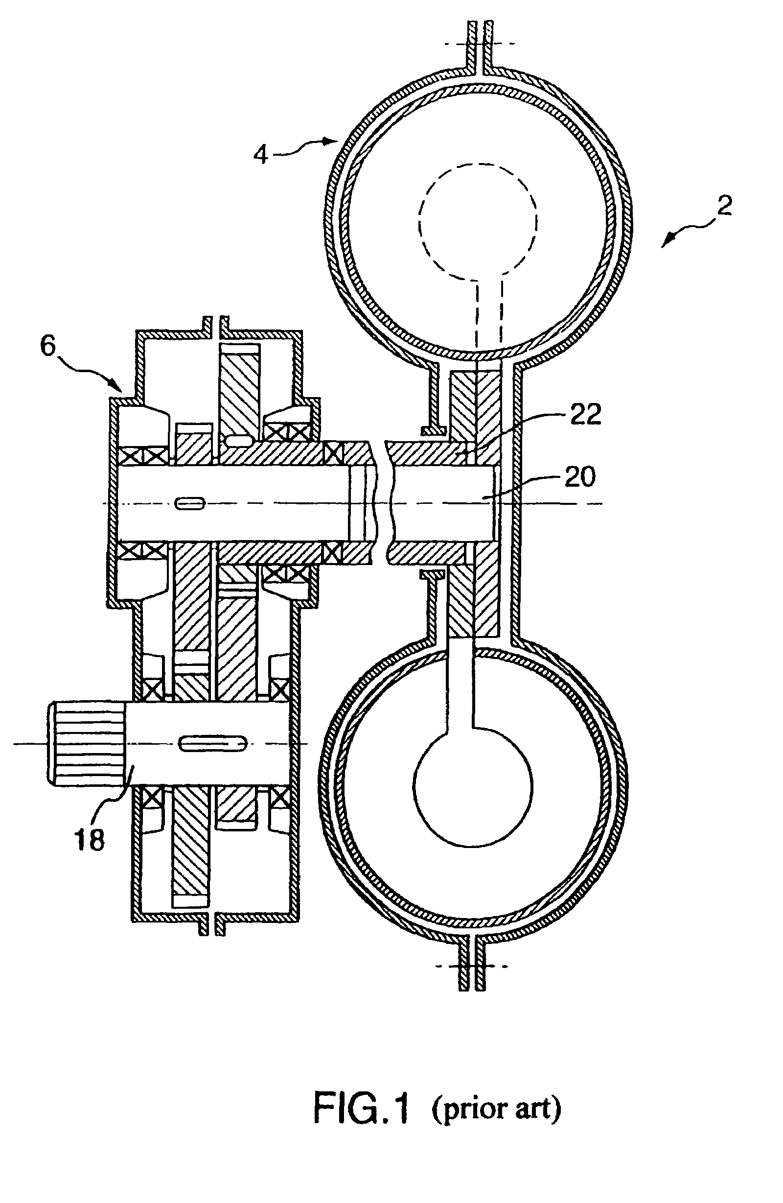
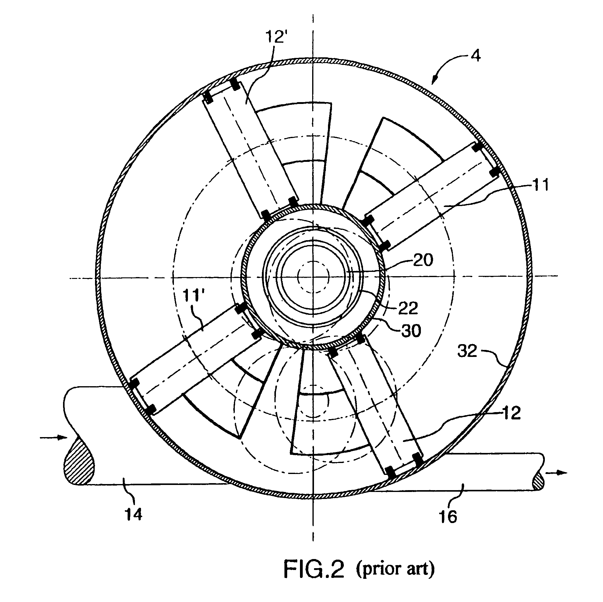
[0041]The engine 2, as shown in FIGS. 1 and 2, has a combustion unit with a toroidal cylinder and vane arrangement 4, in combination with a drive train arrangement for positioning of the vanes, generally shown as 6. The vanes the engine are shown as 11 and 111 being diagonally opposite vanes and commonly attached, and associated vanes 12 and 121 also being diagonally opposed and commonly connected. The pairs of vanes 11 and 111 and 12 and 121 also being diagonally opposed and commonly connected. The pairs of vanes 11 and 111 and 12 and 121 are separately associated with one of the inner coaxial shaft 20 and the outer coaxial shaft 22. Thus, one set of vanes is driven by one shaft and other pair of vanes is driven by the other shaft. The engine also includes an exhaust port 16 and intake port 14 associated with the movement of the vanes and fixed relative to the rotary cylinder defined by the inner cylinder wall 30 and the outer cylinder wall 32.

[0042]The cycle of the engine is shown...


PUM


Abstract

The orbital engine or pump comprising of drive train, having several elliptical gears each rotating around focal point with focal distance defined as function of minimum vanes opening, and toroidal cylinders each having inside two impellers with radial vanes continuously rotating with oscillation through a series of identical elliptical gears with one gear on each impeller shaft and second gears in mesh located on input / output shaft out of phase allowing synchronization of cycles performed in each chamber inside toroidal cylinders positioned planetary to input / output shaft. Some of the chambers could be selectively allocated to perform suction, compression, vacuum and combustion with air, gas, steam and liquid media through efficient internal rotary valves attached to impellers or housing and in most cases, eliminating the need for external valving.

Description

FIELD OF THE INVENTION[0001]The present invention relates to engines and pumps and in particular, relates to orbital engines and pump design improvements, allowing increase of engine power or pumping media volume by increasing an amount of chambers for each toroidal cylinder and planetary attachment of additional toroidal cylinders to common drive train with an additional, simplified valving arrangement, and defining formulas for gear parameters serving design improvements and increase of effectiveness.BACKGROUND OF THE INVENTION[0002]Various designs have been proposed for engines which use rotatable vanes which accelerate and decelerate relative to each other to define the various strokes of a combustion engine. Examples of rotary engines are disclosed in U.S. Pat. No. 3,203,405 and U.S. Pat. No. 3,730,654. These prior art vane engines have relatively complicated arrangements for controlling of the vanes movement and have not proved entirely satisfactory.[0003]The Arov engine / pump ...

Claims


Application Information

Patent Timeline
Patent Type & Authority Patents(United States)
IPC IPC(8): F02B53/00F01C1/344F01C1/00F04C2/00F04C18/00F01C1/077F01C11/00F02B53/02
CPCF01C1/077F01C11/004F02B53/02Y10T74/19884Y02T10/17Y02T10/12
Inventor AROV, ANATOLY
Owner AROV ANATOLY
Why Eureka
Try Eureka