System for improving fuel utilization

a fuel utilization and fuel technology, applied in the direction of combustion air/fuel air treatment, machines/engines, mechanical equipment, etc., can solve the problems of increasing emissions, reducing the amount of no/sub>x/sub>actually produced by the engine, and vaporized fuel being conveyed to the engine's combustion chamber may be subject to condensation, etc., to achieve the effect of improving fuel economy, high air-fuel ratio, and improving fuel economy

Inactive Publication Date: 2009-12-15
VAPOR FUEL TECH
View PDF122 Cites 7 Cited by
  • Summary
  • Abstract
  • Description
  • Claims
  • Application Information

AI Technical Summary

Benefits of technology

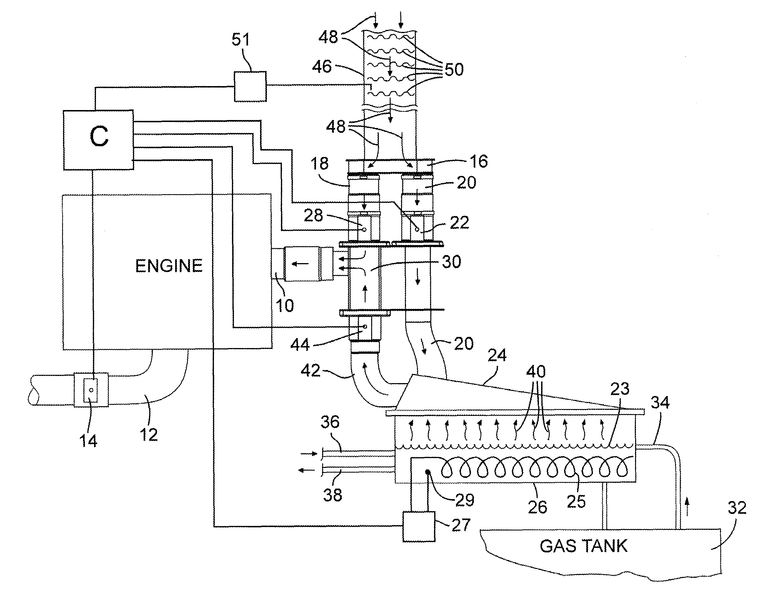
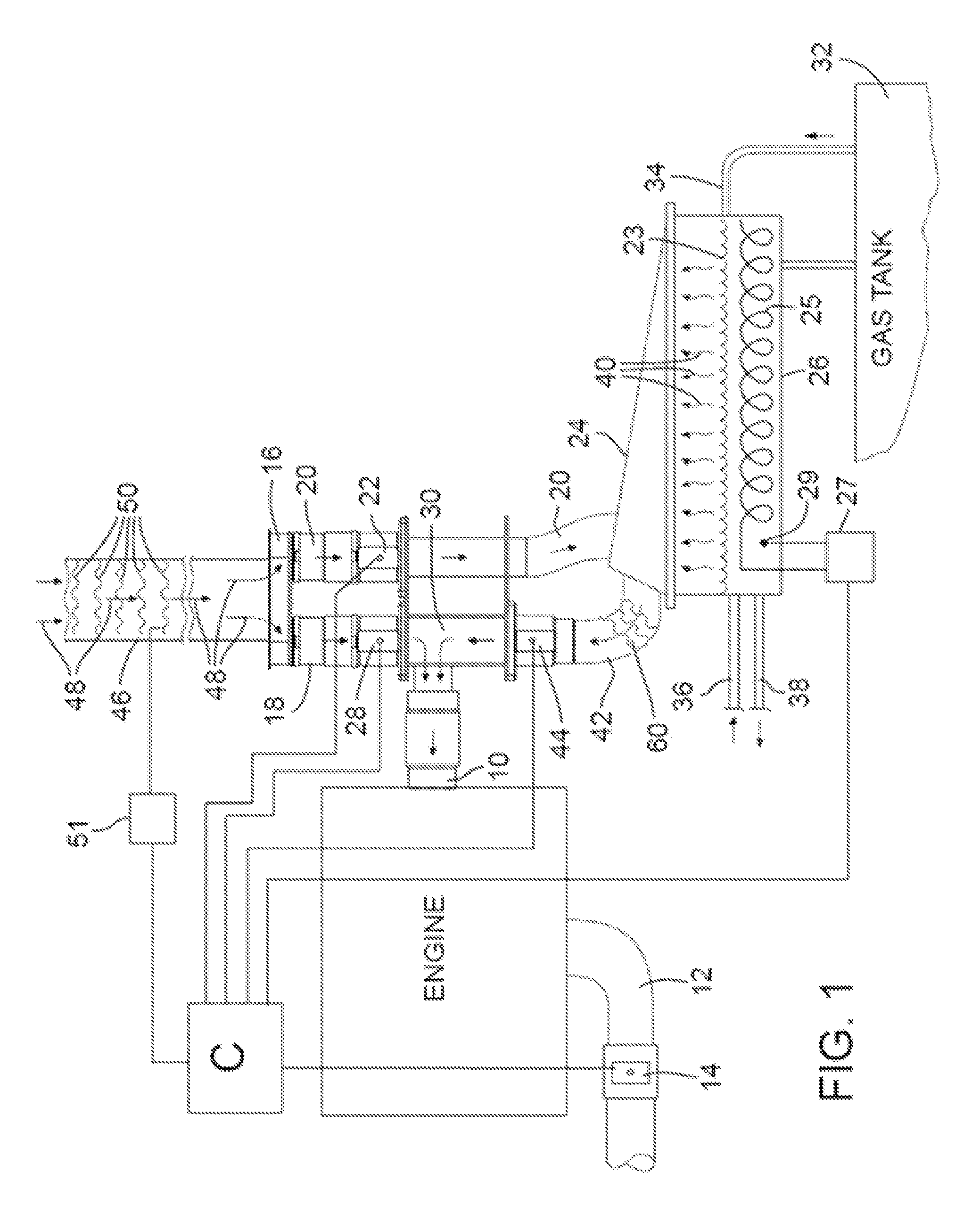
[0010]It is further helpful to elevate the temperature of the ambient air that is mixed with and conveys the fuel vapors from the vaporization chamber prior to entry into the combustion chamber of the engine. As will be discussed more fully hereafter, the mixed air / fuel from the vaporization chamber is further diluted with ambient air, and such further ambient air is also heated whereby the diluted vaporized fuel mixture, upon entering the combustion chamber, is elevated above the temperature of the non-diluted mixture conveyed from the vaporization chamber. As described above, this heating of the air / fuel mixture may help to achieve some of the benefits that improve engine performance, including preventing condensation of the fuel and increasing the flame speed.

Problems solved by technology

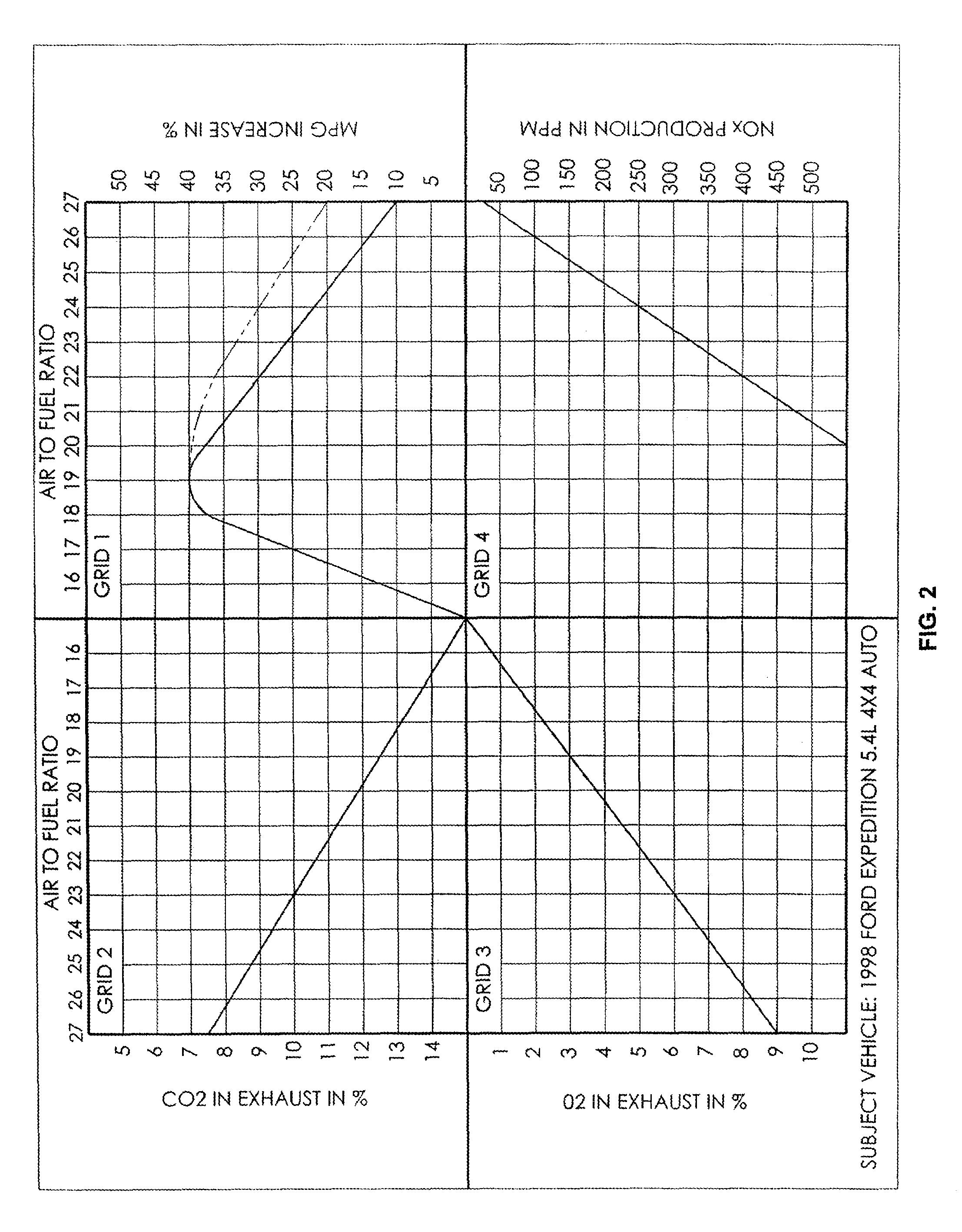
It has been learned, however, that a potential issue may arise with operating at the larger air-to-fuel ratios, in that an undesired increase NOx emissions may result.
However, applicants have found that the amount of NOx actually produced by the engine decreases as the air / fuel ratio increases, and the increase in emissions is a result of the fact that the catalyst cannot reduce even the smaller amount of NOx produced under these conditions.
Further, through observation and testing, applicants have discovered that vaporized fuel being conveyed to the engine's combustion chamber may be subject to condensation during such conveyance.
This may cause the fuel vapors to in part condense and form liquid droplets.

Method used


Image

  • System for improving fuel utilization
  • System for improving fuel utilization
  • System for improving fuel utilization

Examples


Embodiment Construction

[0014]In the following detailed description, reference is made to the accompanying drawings which form a part hereof and in which is shown by way of illustration embodiments in which the invention may be practiced. It is to be understood that other embodiments may be utilized and structural or logical changes may be made without departing from the scope of the present invention. Therefore, the following detailed description is not to be taken in a limiting sense, and the scope of embodiments in accordance with the present invention is defined by the appended claims and their equivalents.

[0015]Various operations may be described as multiple discrete operations in turn, in a manner that may be helpful in understanding embodiments of the present invention; however, the order of description should not be construed to imply that these operations are order dependent.

[0016]The description may use orientation and / or perspective-based descriptions such as up / down, back / front, and top / bottom....


PUM


Abstract

A vapor fuel air mixture supply system for a combustion engine, whereby the mixture of air and fuel vapor is elevated in temperature prior to combustion. The liquid fuel may be vaporized in a fractionation process and further heated to enhance flame speed combustion and improve efficiency of the system.

Description

FIELD OF INVENTION[0001]This invention relates to a system for providing vaporized fuel to engines.BACKGROUND AND BRIEF DESCRIPTION[0002]Vehicles powered by vaporized fuel, such as gasoline, have been the subject of numerous patents over many years. Examples include co-owned U.S. Pat. Nos. 6,681,749 and 6,907,866. The disclosures of such patents are incorporated herein by reference.[0003]Vaporizing the fuel prior to entrance to the cylinder can lead to improved performance, particularly with respect to substantially improved fuel economy. Running an engine “lean” (i.e., at an air to fuel ratio of greater than 15:1) can lead to improved fuel economy. Accordingly, vaporizing the fuel prior to entering the combustion chamber of the engine allows the engine to run at much higher air to fuel ratios than a conventional engine, which in turn leads to improved fuel economy.[0004]It has been learned, however, that a potential issue may arise with operating at the larger air-to-fuel ratios, i...

Claims


Application Information

Patent Timeline
Patent Type & Authority Patents(United States)
IPC IPC(8): F02M31/00
CPCF02M31/045Y02T10/126Y02T10/12
Inventor BUSHNELL, RAYMOND BRYCEDEAN, ANTHONYLEWIS, DANNY ROBERT
Owner VAPOR FUEL TECH
Why Eureka
Try Eureka