Turbine rotor blades

a technology of turbine rotor blades and rotor blades, which is applied in the direction of machines/engines, rotary propellers, liquid fuel engines, etc., can solve the problems of reducing efficiency, increasing weight, and heating problems,

Inactive Publication Date: 2009-12-15
ROLLS ROYCE PLC
View PDF19 Cites 66 Cited by
  • Summary
  • Abstract
  • Description
  • Claims
  • Application Information

AI Technical Summary

Benefits of technology

[0012]In accordance with the present invention there is provided a rotor blade tip arrangement comprising a channel extending along a tip edge in order to inhibit leakage flow laterally across that channel in use, the channel being defined by upstanding winglets with the channel between them and the winglets including apertures to present a coolant flow to mingle with any leakage flow drawn across the channel. The rotor blade having an airfoil portion wherein the rotor blade has an axis from the airfoil portion to the tip edge.

Problems solved by technology

In view of the above it will be appreciated that there is leakage about the peripheral tips of rotor blades of the turbines 16, 17 and 18 during operation and this leakage reduces efficiency with regard to the engine as well as causing heating problems due to the hot combustion gas nature of the leakage flow about the tip.
It is known to inhibit leakage using shrouds on either side of the rotor tip, but generally such shrouding adds significantly to weight and therefore is impractical within most turbine engines particularly if utilised in aircraft.
Nevertheless, as indicated previously, such captured leakage will generally be of a hot combustion gas such that there may be significant heating problems with respect to turbine tips which in themselves are generally formed from thinner sections of material.
These temperatures are limited by the turbine vane and blade materials.
Unfortunately, lingering of leakage flows within the gutter channel 23 as indicated causes significant heating problems, etc.

Method used


Image

  • Turbine rotor blades
  • Turbine rotor blades
  • Turbine rotor blades

Examples


first embodiment

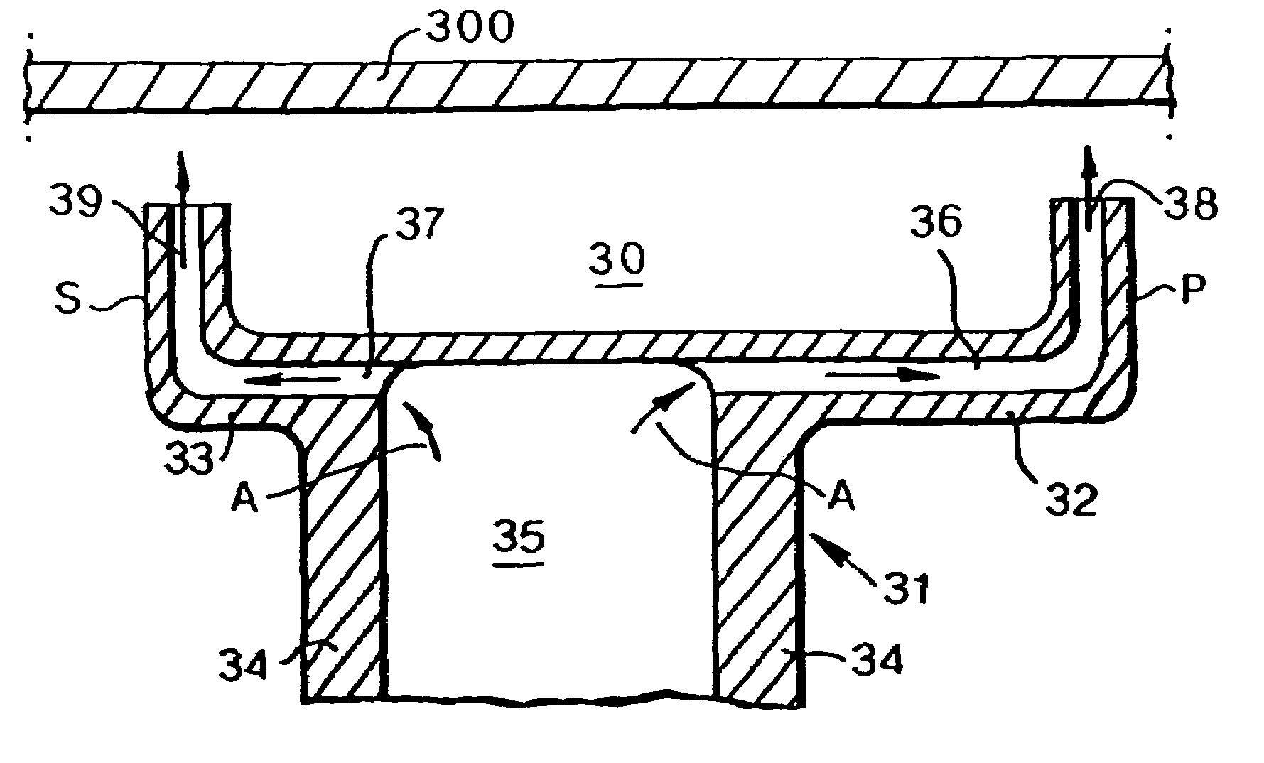
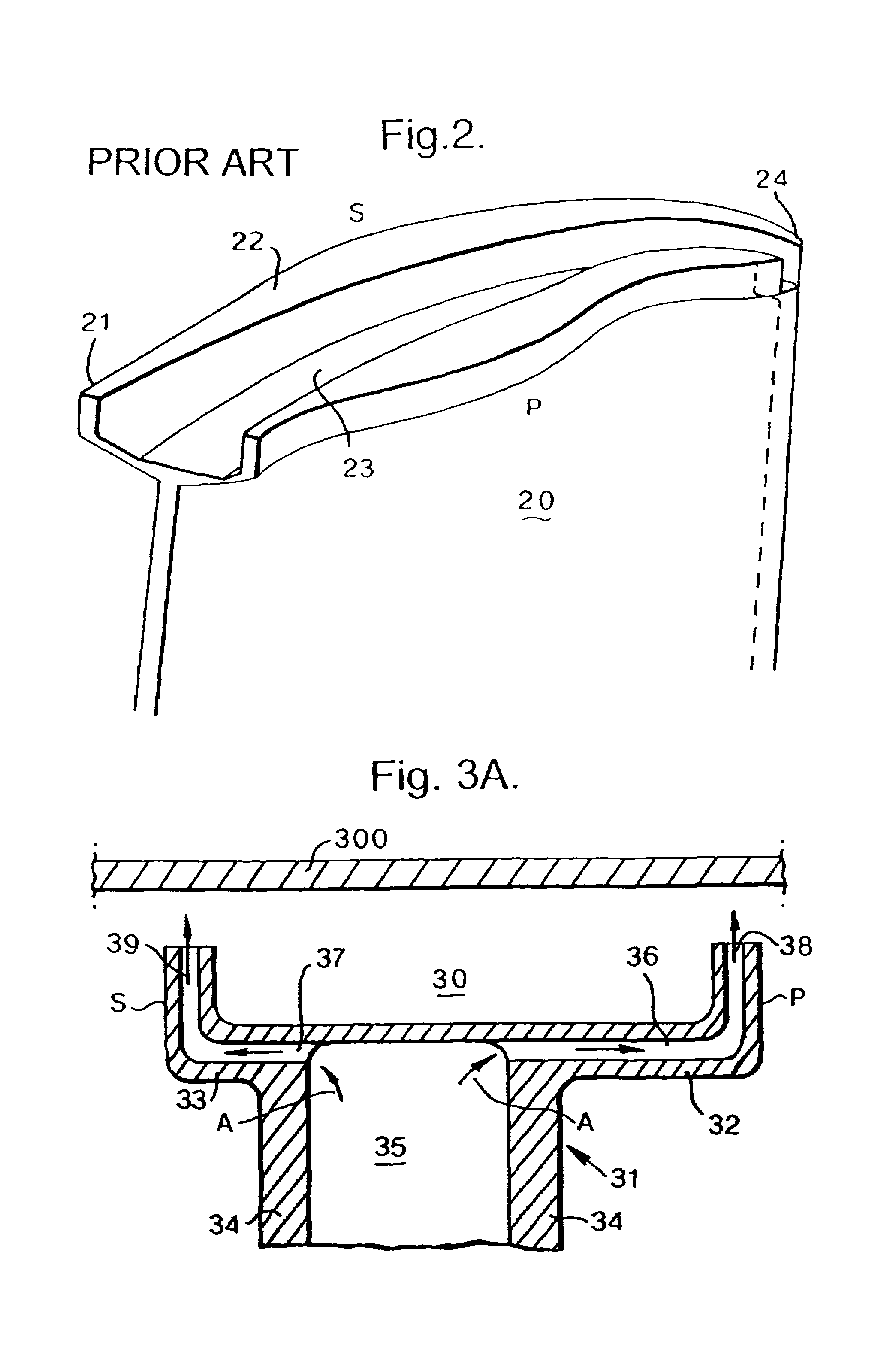
[0034]FIG. 3 illustrates the rotor tip arrangement 31 in accordance with the present invention. The arrangement 31 incorporates winglets 32, 33 which extend laterally from aerofoil walls 34. Within the rotor blade aerofoil there is an internal root passage 35 which supplies coolant air in the direction of arrowheads A to passages 36, 37 within the winglets 32, 33. These passages 36, 37 extend to apertures 38, 39 to project coolant air flow outwardly. As can be seen the winglets 32, 33 include upstanding sections which define a gutter channel 30. In the above circumstances, it will be appreciated that the general configuration of the rotor tip arrangement 31 is similar to that depicted in FIG. 2 except for the features as outlined below.

[0035]Coolant air A is taken from the main aerofoil passage 35 through horizontal holes in the base of each winglet 32, 33.

[0036]The coolant air is ejected at the end of passages through apertures 38, 39. The apertures 38, 39 may continue up the sides...

second embodiment

[0041]FIG. 4 provides a further refinement with respect to at least the pressure side P of a rotor tip arrangement 41 in accordance with the present invention. Thus, the arrangement 41 has an aerofoil wall 44 which extends to a winglet 42 with a coolant flow B entering a passage 46 in the winglet 42 in order to present coolant air D through an aperture 48 in the side of the upstanding section of that winglet 42. Thus, the coolant air B flows over an upper surface 43 of the upstanding winglet 42 section in order to mingle with any leakage flow from the pressure side P. In such circumstances a coolant film is developed over the upstanding portion of the winglet 42 and this in association with the convective cooling through the passage 46 in the winglet 42 as well as mingling of the coolant flow with any leakage flow causes cooling of the arrangement 41. As previously, a stationary casing 400 may also be cooled by impingement of the coolant flow B projected angularly through the apertu...

third embodiment

[0043]In order to further improve resistance to leakage flow from the pressure side to the suction side of a turbine blade it is known to provide additional side cavities or trenches on either side of the open ended gutter channel. FIG. 6 illustrates the present invention in which such side cavities or trenches 67 are provided. Thus, an arrangement 61 comprises turbine aerofoil walls 64 from which winglets 62, 63 extend in order to present upstanding portions incorporating apertures 68a, 68b, 69a, 69b. Coolant air flow C passes through passages in the arrangement 61 in order to present coolant air flow towards a stationary casing 600. As can be seen, an open ended gutter channel 60 is defined between two central upstanding portions 65a, 65b of the winglets 62, 63 whilst cavity winglet sections 66a, 66b define the side cavities or trenches 67.

[0044]FIG. 6 shows how convective cooling in the form of radial holes or apertures 68a, 68b, 69a, 69b could be provided to each of the radial p...


PUM


Abstract

A rotor blade tip arrangement is provided in which winglets extend from the end of rotor blade aerofoil walls. These winglets incorporate passages which extend to coolant apertures or holes in order to present a coolant flow about the tip of the turbine rotor blade. The winglets define at least an open ended gutter channel in order to inhibit leakage flow across the tip arrangement from a pressure side P to a suction side S. The coolant flow facilitates cooling of the arrangement despite any heating caused by leakage flow across the arrangement.

Description

FIELD OF THE INVENTION[0001]The present invention relates to turbine rotor blades and more particularly to the rotor tip arrangements of those turbine rotor blades.BACKGROUND OF THE INVENTION[0002]Operation of turbine engines is well known. Referring to FIG. 1, a gas turbine engine is generally indicated at 10 and comprises, in axial flow series, an air intake 11, a propulsive fan 12, an intermediate pressure compressor 13, a high pressure compressor 14, a combustor15, a turbine arrangement comprising a high pressure turbine 16, an intermediate pressure turbine 17 and a low pressure turbine 18, and an exhaust nozzle 19.[0003]The gas turbine engine 10 operates in a conventional manner so that air entering the intake 11 is accelerated by the fan 12 which produces two air flows: a first air flow into the intermediate pressure compressor 13 and a second air flow which provides propulsive thrust. The intermediate pressure compressor compresses the air flow directed into it before deliver...

Claims


Application Information

Patent Timeline
Patent Type & Authority Patents(United States)
IPC IPC(8): F01D5/18B63H1/14F01D5/20
CPCF01D5/20F05B2240/801Y02T50/676Y02T50/673Y02T50/67F05D2240/81Y02T50/60F01D5/18F01D5/186F05B2210/12
Inventor HARVEY, NEIL WTIBBOTT, IAN
Owner ROLLS ROYCE PLC
Why Eureka
Try Eureka