
Apparatus and method for luminance adjustment of plasma display panel

a technology of luminance adjustment and plasma display panel, which is applied in the direction of instruments, computing, electric digital data processing, etc., can solve the problems of sacrificing the gradation of holistic image, reducing the gray level, and consuming constant power of prior art, so as to achieve the effect of not sacrificing image gradation

Inactive Publication Date: 2009-12-15
CPT TECH GRP
View PDF12 Cites 0 Cited by
  • Summary
  • Abstract
  • Description
  • Claims
  • Application Information

AI Technical Summary

Benefits of technology

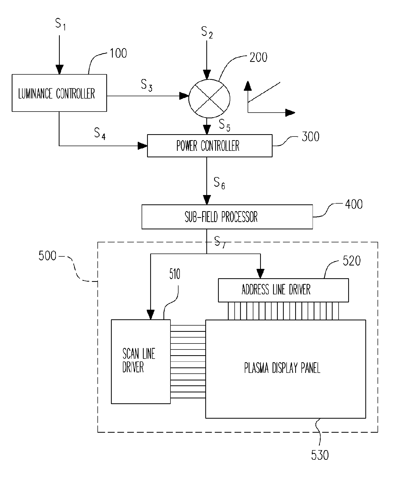
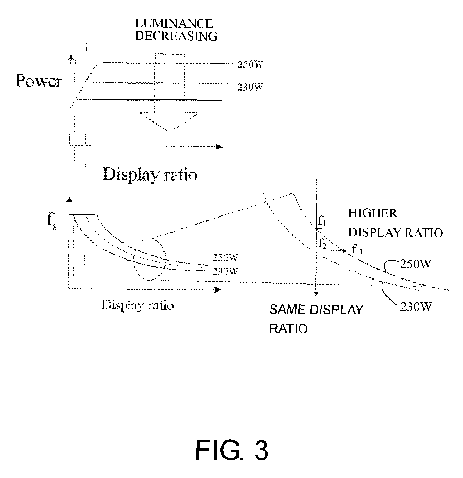
"The present invention provides an apparatus and method for luminance adjustment in a plasma display panel. The apparatus includes a luminance controller, a gray level shifter, and a power controller. The luminance controller outputs a gray level shifting signal and a power adjustment signal. The gray level shifter receives the first luminance video signal and the gray level shifting signal, and adjusts the video signal based on the shifting signal. The power controller receives the adjusted video signal and adjusts the power consumption to achieve the luminance adjustment. The invention provides a method for luminance adjustment that can reduce power consumption while maintaining image gradation. The automatic power controller can adjust the power consumption based on the display ratio shifting signal or the sensor's environment luminance. The invention also provides an apparatus for luminance adjustment that can adjust the power consumption based on the power adjustment signal or the sustain pulse frequency. The technical effects of the invention include reducing power consumption while maintaining image gradation and achieving luminance adjustment through automatic power control."

Problems solved by technology

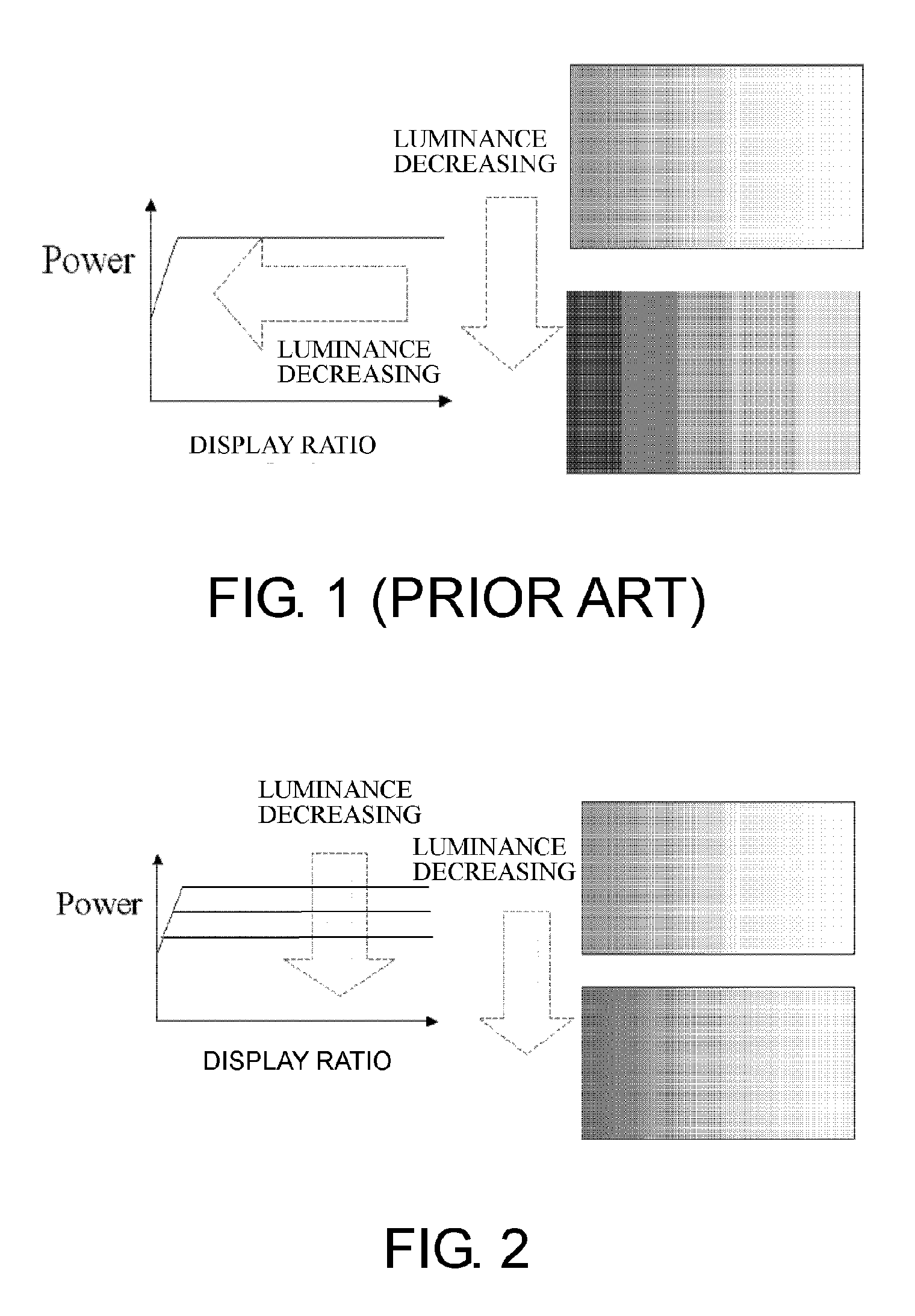
This conventional technology decreases the gray level under a constant consumption power, and sacrifices gradation of holistic image.
In addition, because the power curve remains constant, this prior art still consumes a constant power and cannot timely save power consumption when gray level decreases.

Method used


Image

  • Apparatus and method for luminance adjustment of plasma display panel
  • Apparatus and method for luminance adjustment of plasma display panel
  • Apparatus and method for luminance adjustment of plasma display panel

Examples


Embodiment Construction

[0034]The features of the embodiment for the invention will be explained by reference of drawings. The spirit and scope of this invention are not limit to these embodiments for explanation. It should be noticed that these drawings cannot be looked as a dedicated size or scale. In the scope of this invention, any structure and material described in the following text can be modified properly.

[0035]As shown in FIG. 2, the invention designs a function of luminance adjustment, so that the image gradation can remain when the plasma display panel is under luminance adjustment, and the power consumption can be reduced when the luminance is adjusted down. The difference with prior art is changing the curve between the power to the display ratio. That is, when the luminance is adjusted down, the curve of the power to the display ratio is modified to low power consumption. Likewise, when the luminance is adjusted up, the curve of the power to the display ratio is modified to high power consum...


PUM


Abstract

A luminance adjustment apparatus for a plasma display panel (PDP) is proposed. The luminance adjustment apparatus includes a luminance controller, a gray level shifter and a power controller. The luminance controller outputs a gray level shifting signal and a power adjustment signal. The gray level shifter receives a first luminance video signal and the gray level shifting signal, after the first luminance video signal being level shifted according to the gray level shifting signal, a gray level shifted video signal is output. The power controller is used to receive the gray level shifted video signal and the power adjustment signal, after the gray level shifted video signal being power adjusted by the power adjustment signal, a sub-field controlling signal is output. This enables the preservation of image gradation when adjusting luminance of a video image.

Description

BACKGROUND OF THE INVENTION[0001]1. Field of Invention[0002]The present invention relates to apparatus and method of luminance adjustment of plasma display panel. More particularly, the present invention relates to luminance adjustment method on maintaining original image gradation of plasma display panel.[0003]2. Description of Related Art[0004]Current display apparatus can be separated to two categories that one is using cathode ray tube, and another one is flat panel display. Because flat panel display is lighter and thinner than cathode ray tube display, the display has characteristics of no distortion of display image and no magnetic field interference, flat panel display replaces cathode ray tube display gradually and becomes hot product in the display market.[0005]Usual flat panel displays in the market are liquid crystal display and plasma display panel etc. Technical principle of plasma display panel is using ultraviolet ray produced by inert gases in electric discharge to ...

Claims


Application Information

Patent Timeline
Patent Type & Authority Patents(United States)
IPC IPC(8): G09G3/28
CPCG09G3/2944G09G2320/0606G09G2360/16G09G2330/021G09G2360/144G09G2320/0626
Inventor HSU, CHAO-HUNGLAI, WEI-CHI
Owner CPT TECH GRP
Learn More