Methods, systems and computer program products for characterizing structures based on interferometric phase data

a phase data and structure technology, applied in the field of imaging, can solve the problems of limited resolution of current oct techniques, inability to resolve structures of less than 1-10 m, and few scientific tools which are capable of noninvasively acquiring quantitative information about cell surface profiles, displacements, and motions on the nanometer scal

Active Publication Date: 2009-12-15
DUKE UNIV
View PDF6 Cites 108 Cited by
  • Summary
  • Abstract
  • Description
  • Claims
  • Application Information

AI Technical Summary

Problems solved by technology

However, the resolution of current OCT techniques is generally limited by the coherence length of the illumination source.
Therefore, current OCT techniques may not be able to resolve structures of less than ˜1-10 μm.
However, there are few scientific tools which are capable of noninvasively acquiring quantitative information about cell surface profiles, displacements, and motions on the nanometer scale.
However, some of these techniques which operate noninvasively in the optical far field have so far been limited to spatial resolutions of about λ / 10 or on the order of 50 nm.
These techniques are the diagnostic workhorses of modern nanoscience and nanotechnology, however their innate contact or near-contact operation is by definition invasive to the surface structure under examination.
This invasiveness can take the form of mechanical disruption of the surface structures of interest, or alternatively interfering with or blocking the interaction of surface structures with their environment.

Method used


Image

  • Methods, systems and computer program products for characterizing structures based on interferometric phase data
  • Methods, systems and computer program products for characterizing structures based on interferometric phase data
  • Methods, systems and computer program products for characterizing structures based on interferometric phase data

Examples


Embodiment Construction

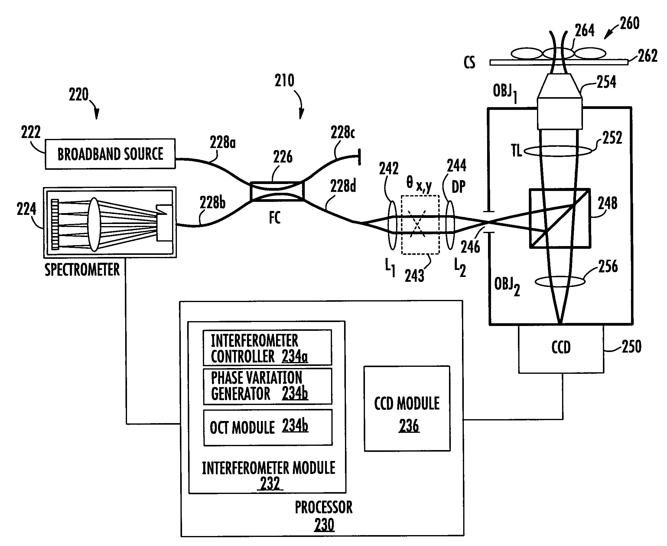
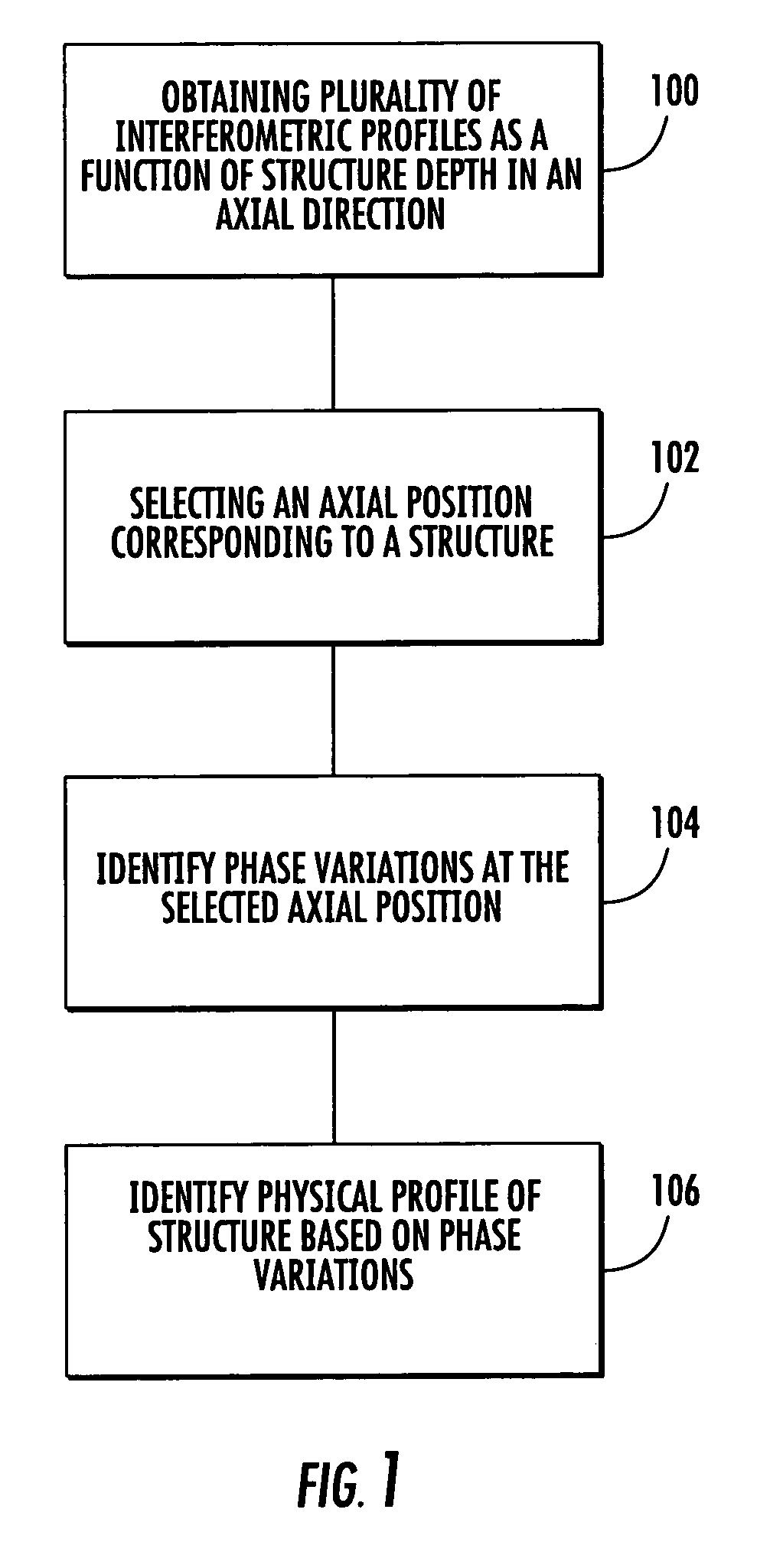
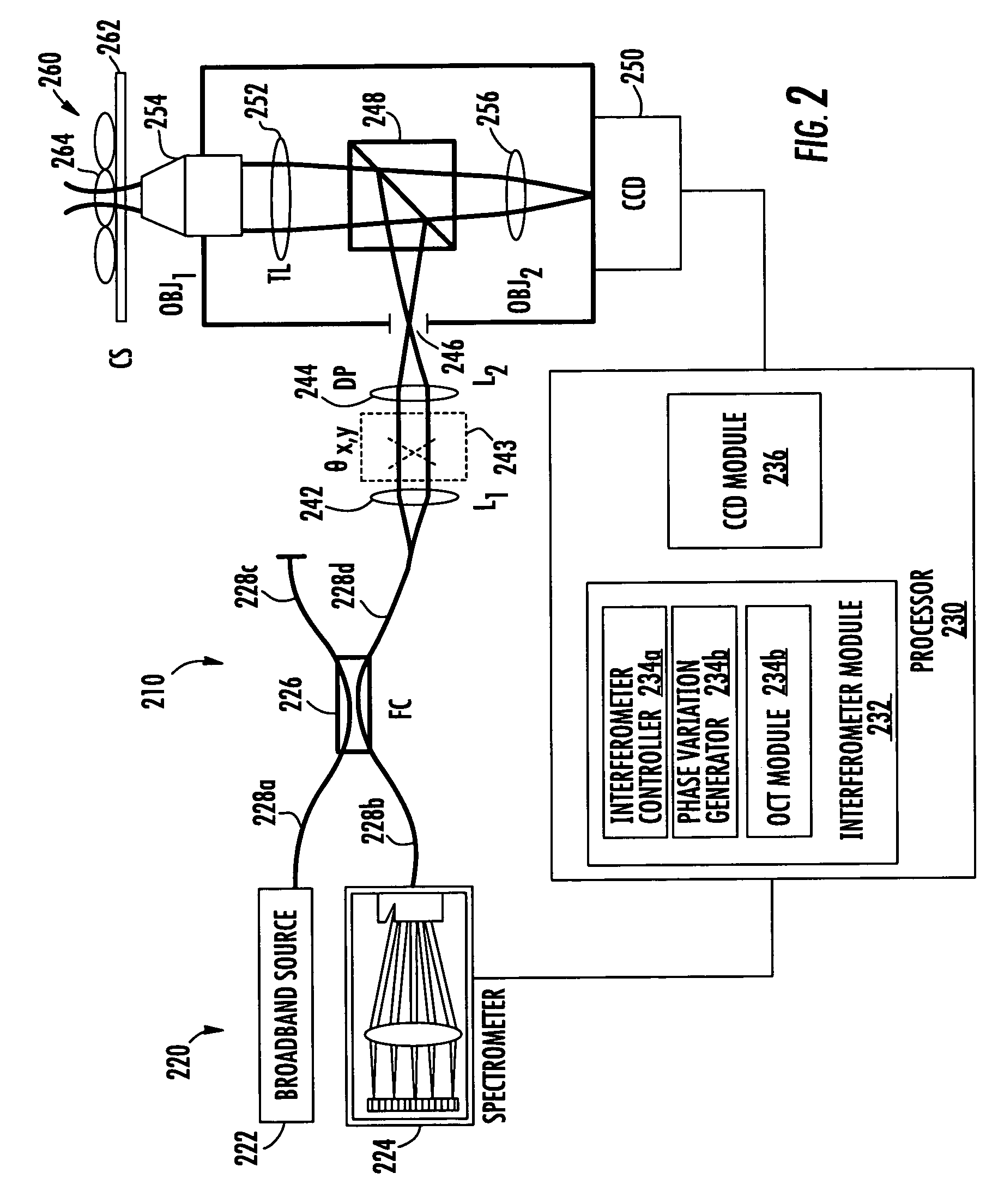
[0008]According to embodiments of the present invention, structure profiles from optical interferometric data can be identified by obtaining a plurality of broadband interferometric optical profiles of a structure as a function of structure depth in an axial direction. Each of the plurality of interferometric optical profiles include a reference signal propagated through a reference path and a sample signal reflected from a sample reflector in the axial direction. An axial position corresponding to at least a portion of the structure is selected. Phase variations of the plurality of interferometric optical profiles are determined at the selected axial position. A physical displacement of the structure is identified based on the phase variations at the selected axial position.

[0009]According to some embodiments of the present invention, a system for identifying structure profiles from optical interferometric data includes an interferometer configured to acquire a plurality of broadba...


PUM


Abstract

Structure profiles from optical interferometric data can be identified by obtaining a plurality of broadband interferometric optical profiles of a structure as a function of structure depth in an axial direction. Each of the plurality of interferometric optical profiles include a reference signal propagated through a reference path and a sample signal reflected from a sample reflector in the axial direction. An axial position corresponding to at least a portion of the structure is selected. Phase variations of the plurality of interferometric optical profiles are determined at the selected axial position. A physical displacement of the structure is identified based on the phase variations at the selected axial position.

Description

RELATED APPLICATIONS[0001]This application claims priority to U.S. Provisional Application Ser. No. 60 / 645,386 filed Jan. 20, 2005, the disclosure of which is hereby incorporated by reference in its entirety.STATEMENT OF GOVERNMENT SUPPORT[0002]This invention was made with Government support under grant number 5R24-EB00243 from the National Institutes of Health. The Government has certain rights to this invention.BACKGROUND OF THE INVENTION[0003]The present invention relates to methods and systems for imaging, and more particularly, to interferometric structure imaging and characterization.[0004]Since its introduction in the early 1990's, optical coherence tomography (OCT) has emerged as a promising imaging modality for micrometer-scale noninvasive imaging in biological and biomedical applications. Its relatively low cost and real-time, in vivo capabilities have fueled the investigation of this technique for applications in retinal and anterior segment imaging in ophthalmology (e.g....

Claims


Application Information

Patent Timeline
Patent Type & Authority Patents(United States)
IPC IPC(8): G01B9/02
CPCG01B9/02083A61B5/0073G01N21/39G01N21/4795G01B9/02004G01B9/0203G01B9/02044G01B9/02057G01B9/02091A61B5/0066A61B5/0059A61B5/7257G01J3/2823G01J3/453G01N2021/1787
Inventor CHOMA, MICHAELIZATT, JOSEPH A.ELLERBEE, AUDREYSARUNIC, MARINKO
Owner DUKE UNIV
Why Eureka
Try Eureka