Method and apparatus for monitoring cable stranding

a technology of stranding and monitoring equipment, which is applied in the field of cable manufacturing, can solve the problems of stranding defect extremely difficult to be detected, affecting the quality of the cable or even imparting the full functionality, and the intensity of the reflected light does not provide a single indication of the presence of faults

Inactive Publication Date: 2009-12-15
PRYSMIAN CAVI E SISTEMI ENERGIA
View PDF23 Cites 4 Cited by
  • Summary
  • Abstract
  • Description
  • Claims
  • Application Information

AI Technical Summary

Benefits of technology

[0020]The Applicant has found that by analysing a surface profile of a stranded cable acquired telemetrically by means of a laser optical triangulation technique, it is possible to ca

Problems solved by technology

During such a process, defects in the cable negatively affect the quality of the cable or even impart the full functionality thereof.
The importance of detecting the presence of stranding defects just after the stranding process is even higher when further protective, reinforcing and/or insulating layers are to be applied to the stranded cable in subsequent manufacturing steps, which would make a stranding defect extremely difficult to be detected.
First of all, the intensity of the reflected light is a parameter which strongly depends on the material and surface characteristics of the single strands. In particular, the intensity of the reflected light depends on the reflectivity of the single s

Method used


Image

  • Method and apparatus for monitoring cable stranding
  • Method and apparatus for monitoring cable stranding
  • Method and apparatus for monitoring cable stranding

Examples


Embodiment Construction

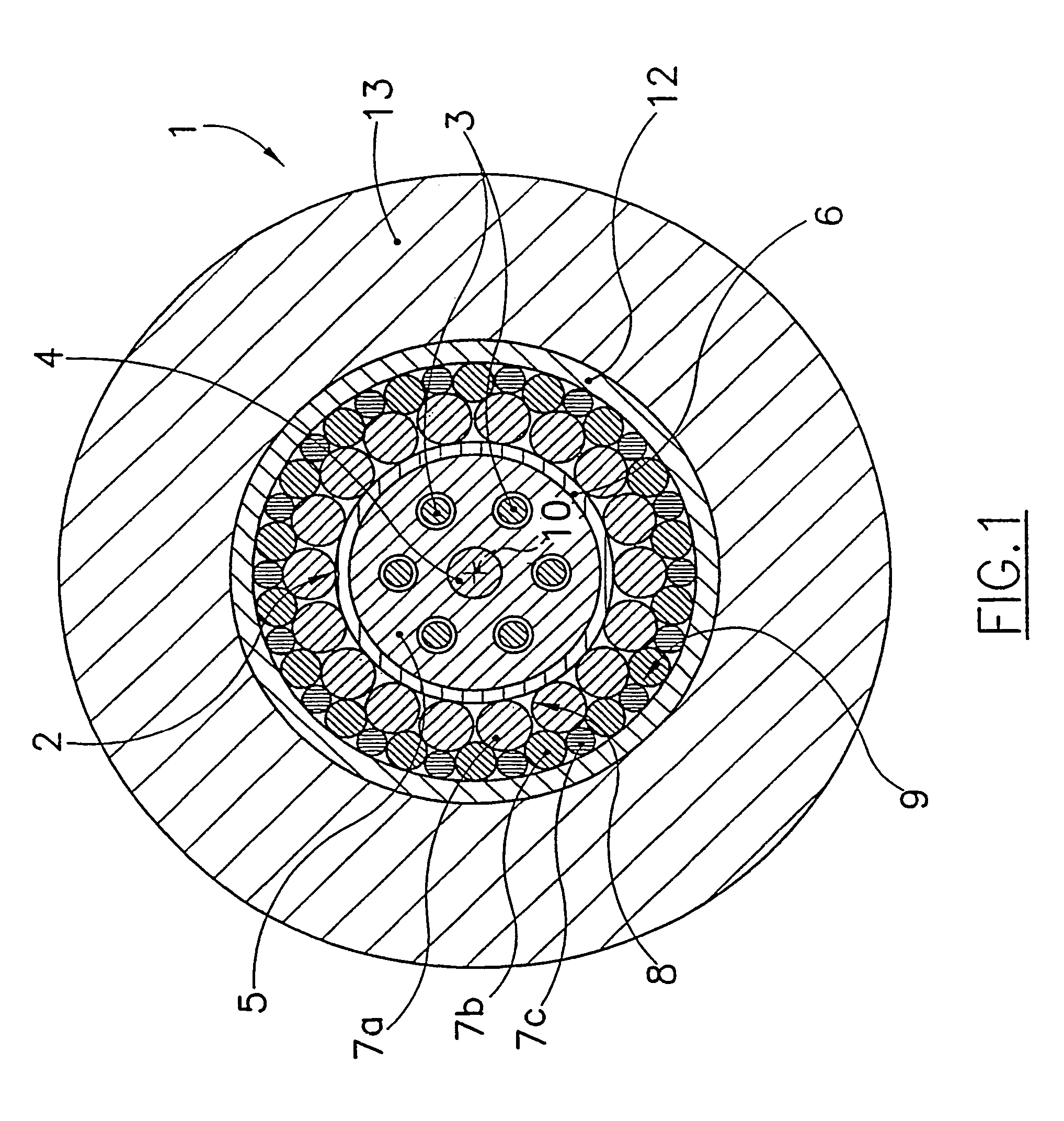
[0075]With reference to FIG. 1, a stranded cable is shown in cross-sectional view. Specifically, the stranded cable shown in FIG. 1 is a submarine cable for optical telecommunications.

[0076]The cable, indicated globally by reference numeral 1, has an axis 10 and comprises a substantially cylindrical central optical core 2. Around the optical core 2 a plurality of protective and reinforcing elements or layers 8, 9, 12 and 13 are provided, which will be described in greater detail later on.

[0077]The optical core 2 comprises a central reinforcing element 4, a polymer layer 5 substantially free of discontinuities, a plurality of (six in the shown example) optical fibers 3 embedded in the polymer layer 5 and a thin sheath 6 made for example of a thermoplastic polymer which coats the polymer layer 5. The optical core 2 may for example have an external diameter of 3 to 4 mm.

[0078]A plurality of strand-like reinforcing elements 7a, 7b and 7c made of steel is provided around the sheath 6.

[00...


PUM


Abstract

A method and a related apparatus for monitoring an external surface of stranded cables, such as submarine cables for optical telecommunications, and electrical energy cables, provide for telemetrically acquiring a profile of the cable external surface by means of a laser optical triangulation technique, obtaining a spectrum of the telemetrically-acquired profile and comparing the obtained spectrum to a previously measured reference spectrum corresponding to a cable free of defects, thereby deducing the presence of defects by differences in the spectra.

Description

CROSS REFERENCE TO RELATED APPLICATIONS[0001]This application is a national phase application based on PCT / EP02 / 09774, filed Sep. 2, 2002, the content of which is incorporated herein by reference, and claims the priority of European Patent Application No. 01203446.8, filed Sep. 11, 2001, and claims the benefit of U.S. Provisional Application No. 60 / 323,332, filed Sep. 20, 2001.BACKROUND OF THE INVENTION[0002]1. Field of the invention[0003]The present invention relates generally to the field of cable manufacturing. More specifically, the invention relates to a method and a related apparatus for monitoring and, in particular, detecting defects in stranded cables such as for example submarine cables for optical telecommunications or electrical energy cables, either submarine or not.[0004]2. Description of the Related Art[0005]Stranded cables comprises in general a central core and one or more layers of strands helically wound around the core.[0006]Submarine cables for optical telecommu...

Claims


Application Information

Patent Timeline
IPC IPC(8): G01N21/00D07B7/02G02B6/44
CPCD07B7/02G02B6/4485G02B6/4479
Inventor CASTIGLIONI, VALTERCECCHI, FELICIANOBECCHI, FRANCESCO
Owner PRYSMIAN CAVI E SISTEMI ENERGIA
Why Eureka
Try Eureka