Method and apparatus for LED panel lamp systems

a technology of led panel lamps and led panel lamps, which is applied in the direction of lighting and heating apparatus, discharge tube luminescnet screens, lighting support devices, etc., can solve the problems of phosphor coated leds with rather low package efficiency, limiting the package efficiency of phosphor coated leds to typically 50-70%,

Active Publication Date: 2009-12-22
SAVANT TECH LLC
View PDF17 Cites 43 Cited by
  • Summary
  • Abstract
  • Description
  • Claims
  • Application Information

AI Technical Summary

Benefits of technology

[0011]Another advantage resides in providing a structure in which phosphor mix and concentration are adjusted remotely.
[0011]Another advantage resides in providing a structure in which phosphor mix and concentration are adjusted remotely.

Problems solved by technology

There are several problems associated with phosphor coated LEDs.
Historically, phosphor coated LEDs have rather low package efficiencies.
In addition, because the phosphors typically are not perfect absorbers of UV or blue radiation, some of the radiation emitted by the LED chip itself is also reflected back onto the structural elements mentioned above.
The light lost due to an absorption of radiation (both initial and converted) by the LED chip, submount, reflector and lead structure limits the package efficiency of phosphor coated LEDs to typically 50-70%.
Furthermore, certain phosphors, such as some from the manganese family, have excessive decay times. When the phosphors with excessive decay times are exposed to high flux emission, i.e., in the close proximity to the LEDs, the effective efficiency is reduced.

Method used


Image

  • Method and apparatus for LED panel lamp systems
  • Method and apparatus for LED panel lamp systems
  • Method and apparatus for LED panel lamp systems

Examples


Embodiment Construction

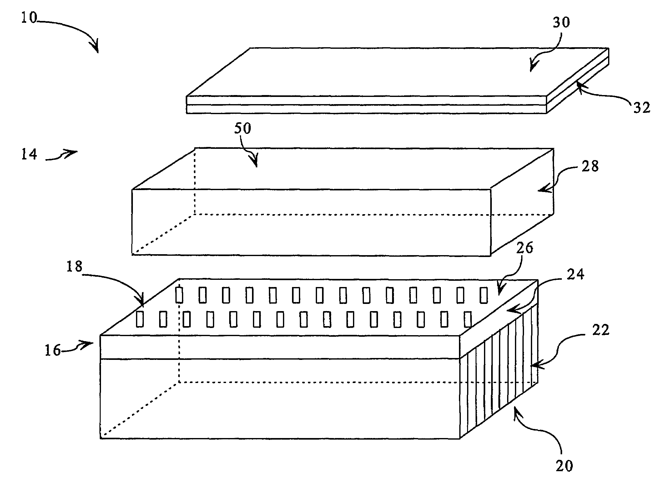
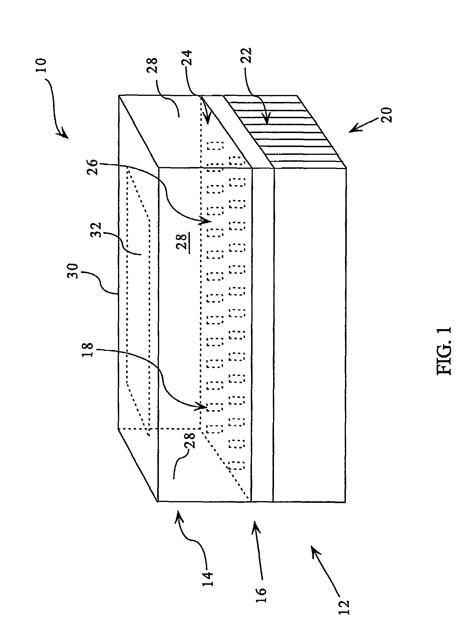
[0018]With reference to FIGS. 1 and 3-4, an LED panel light assembly 10 generally comprises a light engine 12 and an enclosure 14 which surrounds the radiation emitted by the light engine 12. The light engine 12 includes an interconnect system 16 for mounting and connecting light emitting devices or LEDs 18 such as chip or packaged UV LEDs. Preferably, the LEDs 18 have wavelengths less than 510 nm. A heatsink 20, including a plurality of heat dissipating elements such as wings 12, is disposed in thermal connection with the LEDs 18 and the interconnect system 16 to dissipate heat generated by the LEDs 18. Preferably, the interconnect system 16 includes a printed circuit board or an interconnect board or interconnect boards 24 which includes circuitry for powering the LEDs 18 and the leads for electrical communication with a power source. The interconnect boards 24 are selected from commercially available circuit boards, such as the circuit boards available from BERGQUIST, to provide ...


PUM


Abstract

A lighting apparatus (10) comprises a light engine (12) producing ultra violet radiation. An enclosure (14) surrounds a radiation generating area of the light engine (12) to encompass the radiation. At least one wall (28) of the enclosure (14) is substantially reflective of the ultraviolet radiation. The enclosure (14) includes a replaceable top portion (30) which includes a phosphor portion (32). The phosphor portion (32) is spaced from the radiation generating area of the light engine (12) by a height of the enclosure (14).

Description

BACKGROUND[0001]The present application relates to the art of the LED lighting systems that produce visible light. It finds application in general purpose lighting and will be described with particular reference thereto. Those skilled in the art will appreciate applicability of the present application to a variety of applications such as ornamental, special effects lighting, and other.[0002]Typically, the LED lighting systems, which produce white or visible light, incorporate blue LEDs coated with phosphor that converts some of the blue light radiation to a complimentary color, e.g. yellow-green emission. Combined blue, yellow and green emissions produce a white light, which typically has a correlated temperature of about 5000 K and a color rendition index (Ra) of about 70-75.[0003]In recent years, newly developed white LED lighting systems unitize a UV emitting chip coated with phosphors which are designed to convert the UV radiation to visible light. Often, two or more phosphor em...

Claims


Application Information

Patent Timeline
Patent Type & Authority Patents(United States)
IPC IPC(8): F21V23/02H01L33/48F21K99/00F21V9/00H01LH01L25/075H01L33/50H01L33/60H01L33/62
CPCF21K9/00F21Y2101/02H01L25/0753H01L2924/0002Y10S362/80H01L2924/00F21K9/64F21Y2115/10
Inventor WEAVER, JR., STANTON E.STECHER, THOMAS E.SETLUR, ANANT A.SRIVASTAVA, ALOK M.COMANZO, HOLLY A.BECKER, CHARLES A.SOULES, THOMAS F.CHEN, CHEN-LUN HSINGBOMPIEDI, REBECCA A.
Owner SAVANT TECH LLC
Why Eureka
Try Eureka