Stator assembly for a rotary machine

a technology of rotating machines and rotors, which is applied in the direction of stators, machines/engines, liquid fuel engines, etc., can solve the problems of reducing the service life of the rotor, wasting energy, and uselessly heating the gas and adjacent structures by several hundred degrees, so as to reduce the aerodynamic loss, reduce the vibrational stress, and the effect of reducing the loss of aerodynamics

Inactive Publication Date: 2009-12-22
RTX CORP
View PDF7 Cites 15 Cited by
  • Summary
  • Abstract
  • Description
  • Claims
  • Application Information

AI Technical Summary

Benefits of technology

[0025]A principal advantage of the present invention is the efficiency of the rotary machine which results from reducing aerodynamic losses from swirling gases by bounding a cavity in the stator structure with a windage cover. Still another advantage is the durability of the windage cover which results from decreasing vibrational stresses in the windage cover by damping vibrations in the windage cover. In one particular embodiment, the damping of vibrations results from using both coulomb friction and viscous friction to damp vibrations in the windage cover. In one detailed embodiment, damping by viscous friction results from forming the windage cover of relatively thin sheet metal material which permits deflections of the walls of the windage cover in response to operative forces from gases in the cavities adjacent to the windage cover. In one detailed embodiment, an advantage of the method is the cost and weight of the windage cover which results from using material which may be bent, such as sheet metal material, to form the windage cover precursor and to form the windage cover precursor as a continuous ring prior to cutting the precursor to form the segments of the windage cover. In one detailed embodiment, an advantage is the durability of the rotary machine which results from trapping, with the windage cover, structure that might become loose in the cavity bounded by the windage cover. (An example of such structure is a nut and bolt fastener.) An advantage of the windage cover which is produced by the process of attaching, continuous rings prior to cutting the precursor to the windage cover is the efficiency of the rotary machine which results from the circumferential alignment of adjacent circumferential structure of the segments in the installed condition. In one particular embodiment, an advantage of the windage cover which is produced by the process is the alignment of adjacent seal land segments in the installed condition which are attached to the segments of the windage cover.
[0026]The foregoing features and advantages of the present invention will become more apparent in light of the following

Problems solved by technology

(In comparison, the most severe hurricanes have wind velocities of two hundred miles per hour (200 mph) which will cause storm surges in oceans of eighteen (18) feet and may cause catastrophic building failures.)
These winds are gases dragged along by the rotor assembly and constantly take energy from the rotor assembly, and then lose this energy to the stator assembly by doing work on the adjacent structures through friction forces and by slamming into the irregular surfaces extending into the cavity.
The energy is transformed from the useful kinetic energy of rotation into heat, uselessly heating the gases and adjacent structures by several hundred degrees, and decreasing the efficiency of the engine.
This may require the use of heavier and more expensive materials more forward in the engine than would otherwise be required if the mass of such swirling gases could be reduced.
However, the structures add weight to the engine, which reduces engine efficiency.
But then another problem arises because of the close proximity of the rotor assembly to the stator assembly and to any structure provided to stator assembly.
These pressure pulses take the form of significant acoustic energy which slams into the structure of the adjacent stator assembly and causes significant vibrations in these structures.
As a result, experience has shown that destructive vibrations can occur in the adjacent structure and that such structures must be relatively strong (with a concomitant increase in weight) to withstand the severe winds and acoustic energy adjacent these cavities.

Method used


Image

  • Stator assembly for a rotary machine
  • Stator assembly for a rotary machine
  • Stator assembly for a rotary machine

Examples


Embodiment Construction

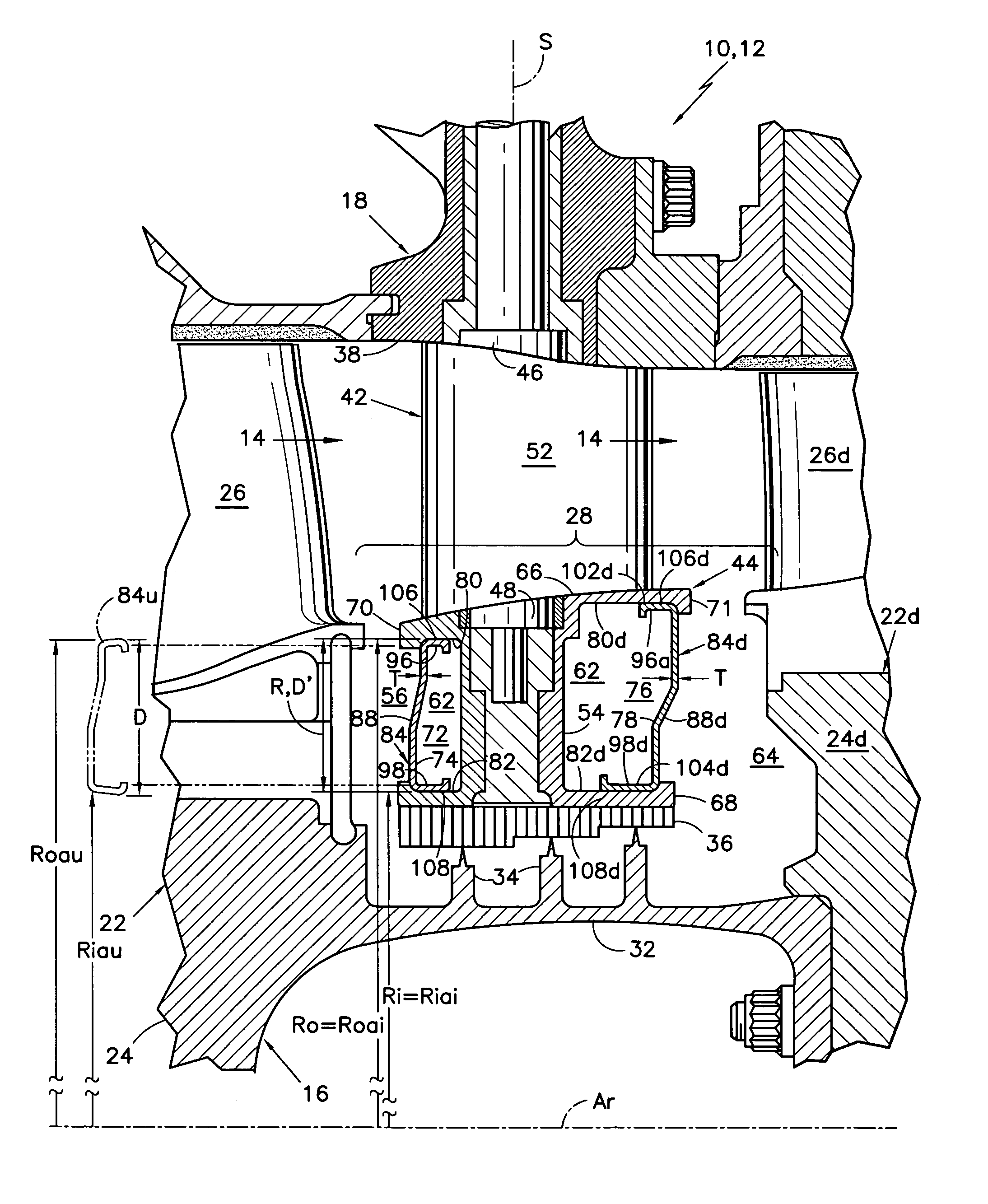
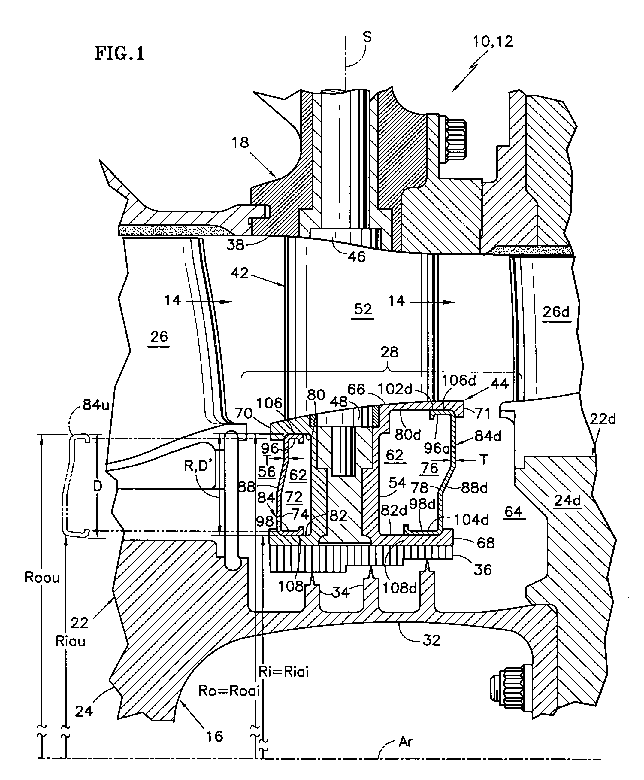
[0041]FIG. 1 shows is a side elevation, cross sectional view of a rotary machine 10, such as a gas turbine engine, having a compression section 12. A portion of the compression section is shown in FIG. 1 and is partially broken away for clarity. The engine includes an axis of rotation Ar and an annular flowpath 14 for a stream of working medium gases. The annular flowpath extends axially through components of the compression section. These components include a rotor assembly 16 and a stator assembly 18 which extend circumferentially about the axis of rotation Ar.

[0042]The rotor assembly 16 includes a first rotor disk and blade assembly 22 and a second rotor disk and blade assembly 22d. Each rotor disk and blade assembly 22, 22d has a rotor disk 24, 24d and an array of rotor blades, as represented by the rotor blades 26, 26d. The rotor blades extend outwardly across the working medium flow path into proximity with the stator assembly. The second rotor disk and blade assembly 22d is s...


PUM

PropertyMeasurementUnit
total thicknessaaaaaaaaaa
velocitiesaaaaaaaaaa

Abstract

A stator assembly having a windage cover for structure adjacent to a cavity bounded by rotating elements in a rotary machine is disclosed. Various construction details are developed for damping vibrations in the windage cover as the windage cover bounds a cavity having swirling high velocity gases that are capable of transmitting acoustic energy and kinetic energy to adjacent structure. In one detailed embodiment, the windage cover in the uninstalled condition has diverging arms that are resiliently compressed during installation to exert a frictional force on the adjacent structure.

Description

BACKGROUND OF THE INVENTION[0001]This invention relates to stator assemblies of the type used in rotary machines that have stator vanes, such as gas turbine engines. More particularly, this invention relates to structure for aerodynamically smoothing surfaces that bound a cavity extending between a rotor assembly and a stator assembly.[0002]Rotary machines are used to transfer energy between a flow path for a stream of working medium gases and rotating elements inside the machine. There are many examples of such machines in widely disparate fields of endeavor.[0003]Axial flow gas turbine engines for industrial purposes and for propelling aircraft are one example of such machines. These engines typically have a compression section, a combustion section and a turbine section disposed about an axis of rotation. An annular flow path for working medium-gases extends axially through the sections of the engine. The gases are compressed in the compression section. Fuel is burned with the ga...

Claims


Application Information

Patent Timeline
Patent Type & Authority Patents(United States)
IPC IPC(8): F01D11/02F01D17/16
CPCF01D11/001Y02T50/671Y10T29/4932Y10T29/49813Y10T29/49792Y10T29/49789Y02T50/60F01D17/162
Inventor DUESLER, PAUL W.LOFFREDO, C. VINCENTNICOLSON, MATTHEW D.PAWLACZYK, RICHARD J.
Owner RTX CORP
Why Eureka
Try Eureka