Device for magnetically suspending a rotor

a rotor and magnetic suspension technology, applied in the direction of relays, magnetic bearings, mechanical devices, etc., can solve the problems of loss of sensitivity, coupling between radial force and axial force, loss of capacity, etc., and achieve the effect of large capacity

Active Publication Date: 2009-12-22
SKF MAGNETIC MECHATRONICS
View PDF9 Cites 37 Cited by
  • Summary
  • Abstract
  • Description
  • Claims
  • Application Information

AI Technical Summary

Benefits of technology

[0016]The present invention seeks to remedy the above-mentioned drawbacks and to provide a magnetic abutment of diameter that is minimized for given capacity, while avoiding creating magnetic leakage looped in the machine and presenting a risk of leading to side effects harming proper operation of other devices situated in the vicinity of an axial magnetic bearing of a device for magnetically suspending a rotor.
[0025]In general, the device of the invention makes it possible to provide a magnetic suspension that includes an axial magnetic abutment having large capacity and without magnetic leakage.

Problems solved by technology

More particularly, the circuit 101 leads to the radial bearing 30 being magnetized, thereby leading to a loss in its capacity and creating coupling between the radial force and the axial force.
The circuit 102 leads to magnetization of the position sensors, leading to a loss of sensitivity thereof and creating coupling between measurements and the axial force.
The device shown in FIG. 7 thus presents the major drawback of creating significant amounts of magnetic leakage.
Unfortunately, in various applications, given the high speed of rotation of the rotor, it is not possible to increase the diameter of the rotor armature in the axial bearing beyond certain limits, so that implementing multiple coils within an axial bearing becomes problematic because of the residual active surface areas no longer being large enough, thereby limiting the capacity of the axial bearing.

Method used


Image

  • Device for magnetically suspending a rotor
  • Device for magnetically suspending a rotor
  • Device for magnetically suspending a rotor

Examples


Embodiment Construction

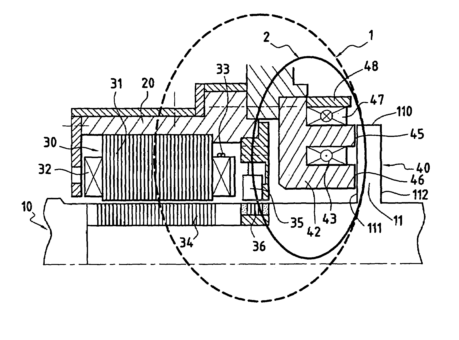
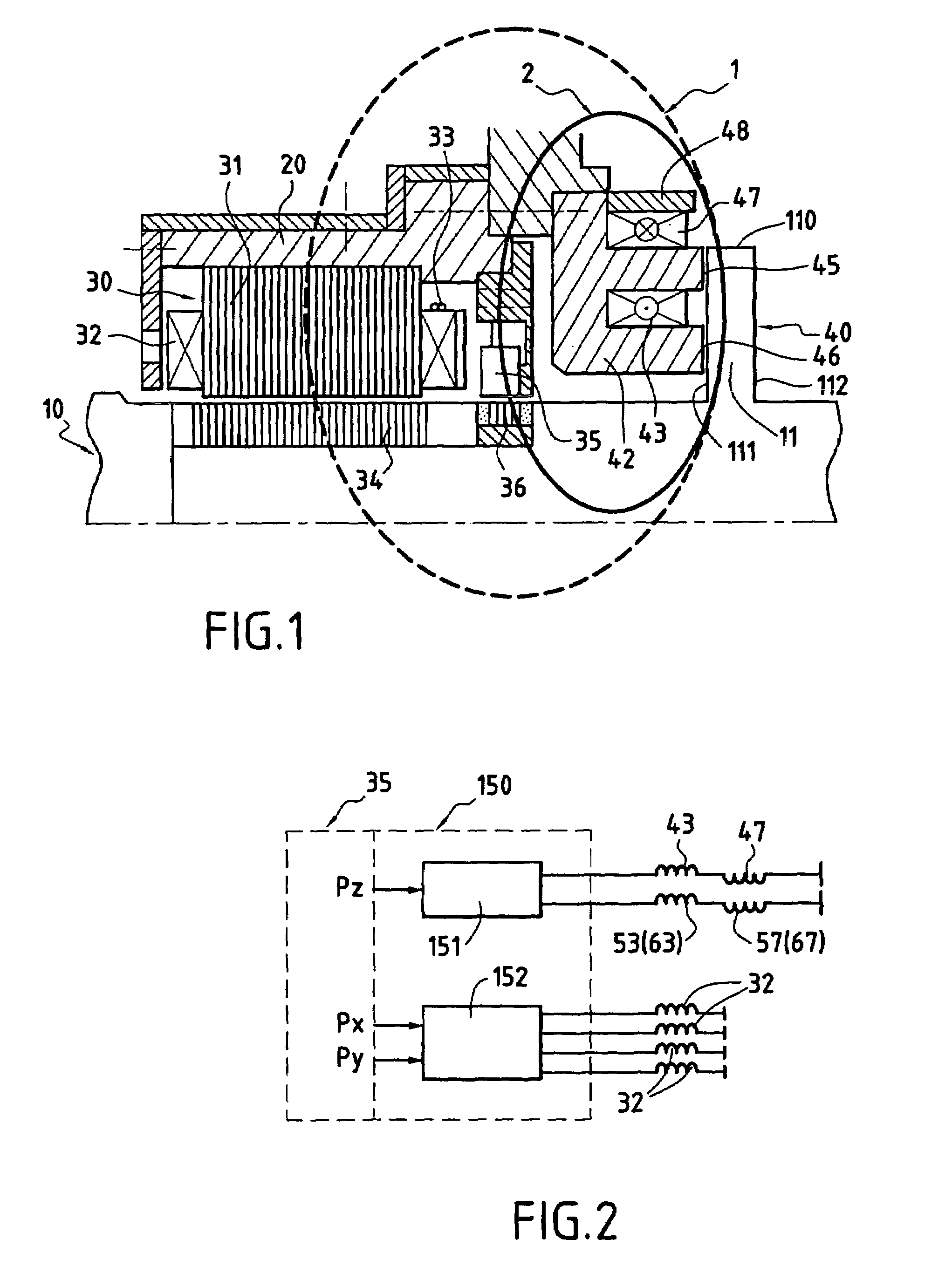
[0033]FIG. 1 shows an embodiment of a device for magnetically suspending a rotor 10, the device essentially comprising an axial active magnetic bearing 40 and a radial active magnetic bearing 30 that enable the rotor 10 to be supported without contact relative to a stationary structure 20.

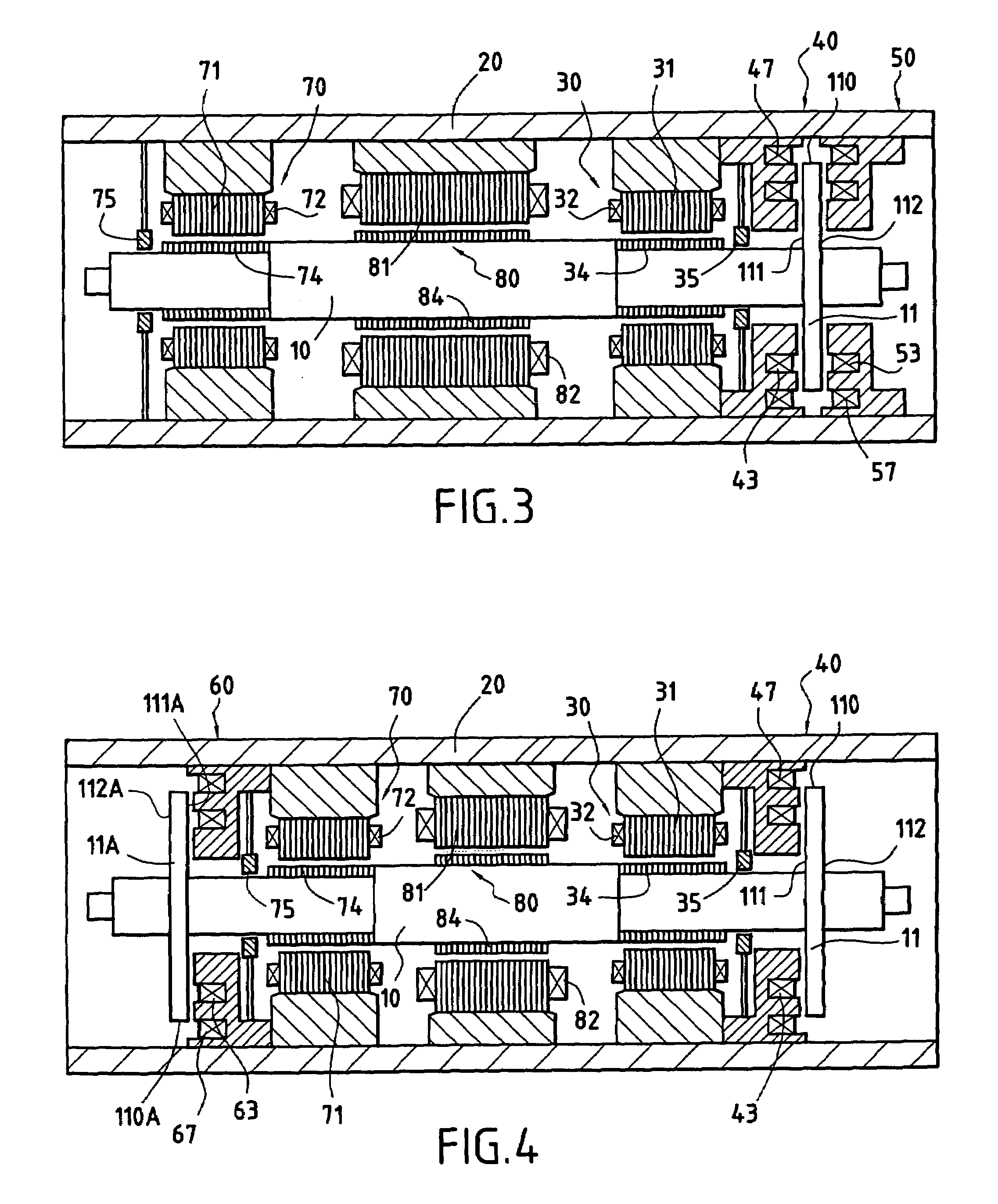
[0034]FIG. 1 shows only one radial magnetic bearing 30 disposed in the vicinity of the axial magnetic bearing 40. Nevertheless, a second radial bearing 70, that may optionally be of the same type as the radial bearing 30, is normally implemented in the vicinity of another portion of the rotor 10 at a certain distance from the radial bearing 30 in order to ensure that the rotor is held completely in the radial direction (see FIGS. 3 and 4).

[0035]A second axial magnetic bearing analogous to axial bearing 40 may also be installed in the vicinity of the axial bearing 40 symmetrically relative to the rotor armature 11 that is constituted in the form of a disk perpendicular to the axis of the rotor 10. U...


PUM


Abstract

The device for magnetically suspending a rotor relative to a structure comprises at least one axial active magnetic bearing with a main electromagnet coil disposed in a stator and having load-bearing surfaces placed facing an armature extending essentially perpendicularly to the axis of the rotor. A device for detecting the axial position of the rotor is associated with circuits for servo-controlling the current carried by the main electromagnet coil. A compensation coil is disposed close to the main electromagnet coil, but in a position that is situated away from the load-bearing surfaces of the stator that co-operate with the rotor armature. The compensation coil is connected in series with the main electromagnet coil, but carries current in the opposite direction to that carried by said main electromagnet coil. The device constitutes an axial abutment of optimized capacity without magnetic leakage.

Description

[0001]This application claims priority to French application No. 06 50121 filed Jan. 13, 2006.[0002]The present invention relates to a device for magnetically suspending a rotor relative to a structure, the device comprising at least one axial active magnetic bearing with a main electromagnet coil disposed in a first stator secured to the structure and having load-bearing surfaces placed facing a first rotor armature extending substantially perpendicularly to the axis of the rotor and presenting a free peripheral end, a device for detecting the axial position of the rotor, and circuits for servo-controlling the current flowing in the main electromagnet coil.BACKGROUND OF THE INVENTION[0003]A device of this type is already known, e.g. as shown in FIG. 7, that comprises an axial bearing 120 comprising a stator 122 of ferromagnetic material presenting an annular housing concentric with the axis of the rotor 10 for receiving a coil 123. The active surfaces 125, 126 of the stator 122 sit...

Claims


Application Information

Patent Timeline
Patent Type & Authority Patents(United States)
IPC IPC(8): H02K7/09F16C39/06
CPCF16C32/0459F16C32/047F16C32/0476F16C32/0489H02K7/09
Inventor BRUNET, MAURICEBAUDELOCQUE, LUCLAPIERRE, ARMAND
Owner SKF MAGNETIC MECHATRONICS
Why Eureka
Try Eureka