Organ access device and method

a technology of access device and body, applied in the direction of medical science, surgery, diagnostics, etc., can solve the problems of not being able to use head frame technology, target location is hidden within the subject, and screw may not center, so as to improve accuracy and ease of use.

Active Publication Date: 2009-12-22
MEDTRONIC INC
View PDF314 Cites 95 Cited by
  • Summary
  • Abstract
  • Description
  • Claims
  • Application Information

AI Technical Summary

Benefits of technology

[0009]The above mentioned problems of adjustability are addressed by the present invention and will be understood by reading and studying the following specification. De

Problems solved by technology

A drawback to catheter insertion procedures is that the target location is hidden within the subject.
This was not possible using head frame technology, where a subject needed to remain secured inside a head frame until after completion of the surgical procedure.
A difficulty with this procedure arises in location tolerance when the insertion guide

Method used


Image

  • Organ access device and method
  • Organ access device and method
  • Organ access device and method

Examples


Embodiment Construction

[0034]In the following detailed description of the invention, reference is made to the accompanying drawings which form a part hereof, and in which is shown, by way of illustration, specific embodiments in which the invention may be practiced. In the drawings, like numerals describe substantially similar components throughout the several views. These embodiments are described in sufficient detail to enable those skilled in the art to practice the invention. Other embodiments may be utilized and structural changes, logical changes, etc. may be made without departing from the scope of the present invention.

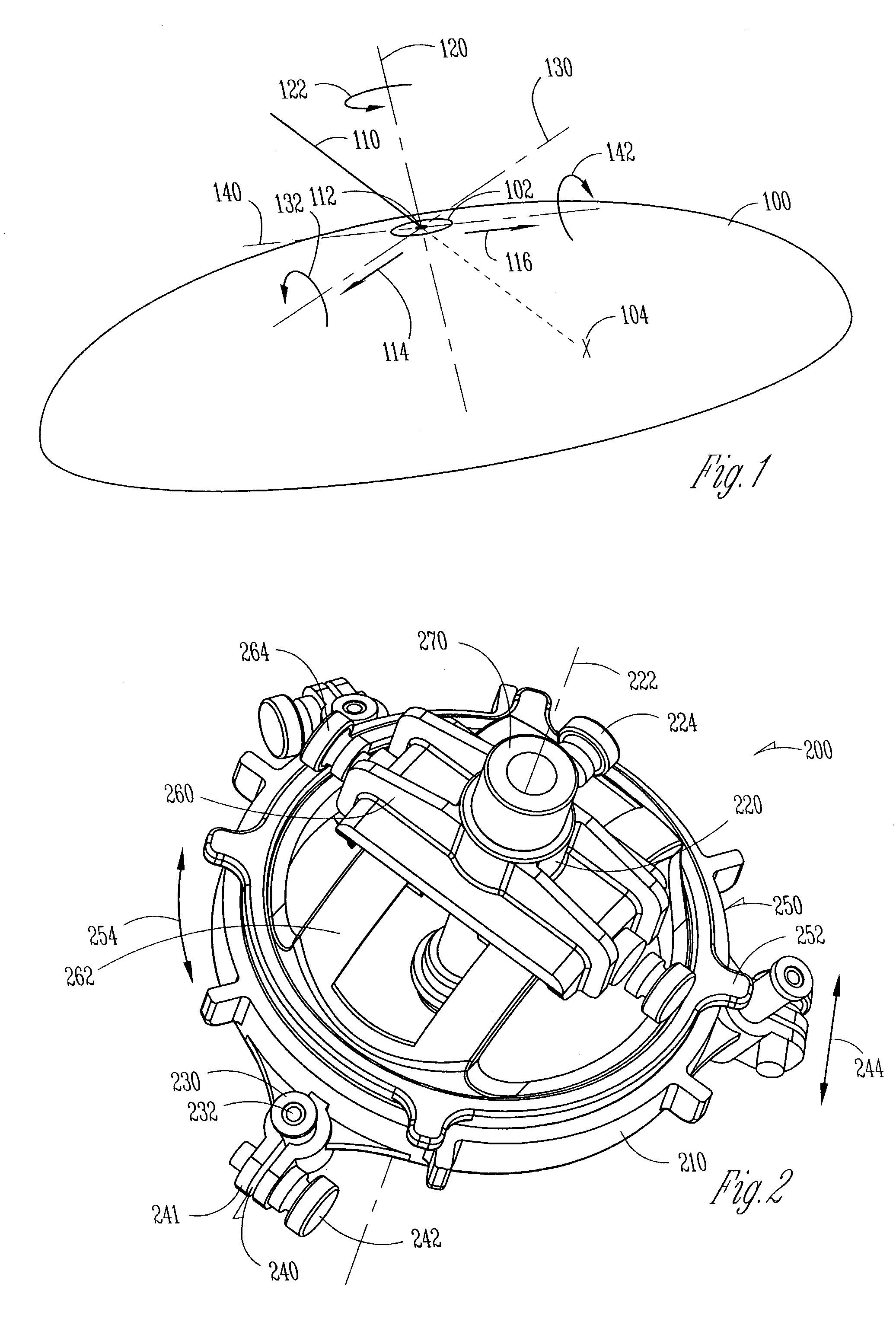
[0035]FIG. 1 shows a subject surface 100 along with one possible coordinate system for defining locations and orientations with respect to the subject. In one embodiment, the subject surface 100 includes a skull of a subject. An opening 102 in the subject surface is shown, along with a target location 104 within the subject. In one embodiment, the opening 102 includes a burr hole. A...


PUM


Abstract

An insertion guide is shown that includes at least one insertion point adjustment device. A user such as a surgeon is able to adjust a lateral position of an insertion point to more precisely center the insertion point within an opening in a subject, such as a burr hole. Selected insertion guide devices further include a centering guide that easily indicates to a user when the insertion point is substantially centered within the opening in the subject. Selected insertion guide devices include adjustability of multiple degrees of rotational freedom of an insertion axis. Selected insertion guide devices further permit a user to fix multiple degrees of rotational freedom of an insertion axis using a single locking device. Tissue damage due to an attachment procedure of an insertion guide device is reduced using selected configurations described herein.

Description

FIELD OF THE INVENTION[0001]The present invention relates to guiding devices. Specifically, the invention relates to trajectory guidance of medical devices for procedures such as catheter or lead insertion.BACKGROUND OF THE INVENTION[0002]A desire to reduce the disturbance of tissue during surgical procedures drives methods and devices for surgical insertion such as catheter insertion. The term “catheter” as used in this document is a broad term that generally describes an elongated tube for insertion into a region of a subject. Catheters include, but are not limited to, drug delivery catheters, optical catheters, micro-catheters, host catheters, etc. A small diameter catheter can be inserted into a subject along an insertion trajectory towards a target location within the subject with a minimal disturbance to surrounding tissue.[0003]A drawback to catheter insertion procedures is that the target location is hidden within the subject. Only a small opening in the subject allows inser...

Claims


Application Information

Patent Timeline
IPC IPC(8): A61B5/05A61B17/34A61B19/00
CPCA61B19/201A61B2019/5416A61B2019/5287A61B2017/3405A61B2090/363A61B2090/3916A61B90/11B33Y80/00
Inventor SOLAR, MATTHEW S.
Owner MEDTRONIC INC
Why Eureka
Try Eureka