Valved sheath introducer for venous cannulation

a technology of valves and introducers, which is applied in the direction of functional valve types, infusion syringes, catheters, etc., can solve the problem of not being able to resume the original position, and achieve the effect of optimal sealing

Active Publication Date: 2009-12-29
CR BARD INC
View PDF329 Cites 130 Cited by
  • Summary
  • Abstract
  • Description
  • Claims
  • Application Information

AI Technical Summary

Benefits of technology

[0005]Accordingly, the present invention is directed to a valved sheath introducer for venous cannulation. In one embodiment of the invention, the valve in the introducer includes a thin disk with a central slit and includes features such as opposing anchors to allow stretching of the disk when a medical device is inserted therethrough, a thickened central portion through which a self-sealing slit is positioned, which promotes optimal resealing upon removal of a medical device, and mechanical or other means of splitting the disk simultaneous to the breaking and separating of a sheath handle from an inserted medical device. In one embodiment, the thickened central portion or island has a concave surface. Some embodiments of the valve include slits or notches aligned with the central slit to facilitate separation of the valve when the sheath and handle are removed from an inserted medical device.
[0007]In one aspect of the valved sheath introducer, the valve is designed to provide optimal sealing when removing an instrument, such as a dilator. The optimal sealing occurs due to the configuration of the valve, such as a central portion or island and one or more anchoring members, and the way in which the valve is tightly held between a handle and a cap. Thus, upon removal of an instrument from the introducer sheath, the valve body, which is stretched as the instrument is inserted therethrough, rebounds toward the handle but cannot resume its original position due to the pressure exerted by the cap and the handle. The result is a bunching or duckbill effect of the valve that provides a desirable seal.

Problems solved by technology

Thus, upon removal of an instrument from the introducer sheath, the valve body, which is stretched as the instrument is inserted therethrough, rebounds toward the handle but cannot resume its original position due to the pressure exerted by the cap and the handle.

Method used


Image

  • Valved sheath introducer for venous cannulation
  • Valved sheath introducer for venous cannulation
  • Valved sheath introducer for venous cannulation

Examples


Embodiment Construction

[0024]The following detailed description should be read with reference to the drawings, in which like elements in different drawings are identically numbered. The drawings, which are not necessarily to scale, depict selected embodiments and are not intended to limit the scope of the invention. The detailed description illustrates by way of example, not by way of limitation, the principles of the invention. This description will clearly enable one skilled in the art to make and use the invention, and describes several embodiments, adaptations, variations, alternatives and uses of the invention, including what is presently believed to be the best mode of carrying out the invention.

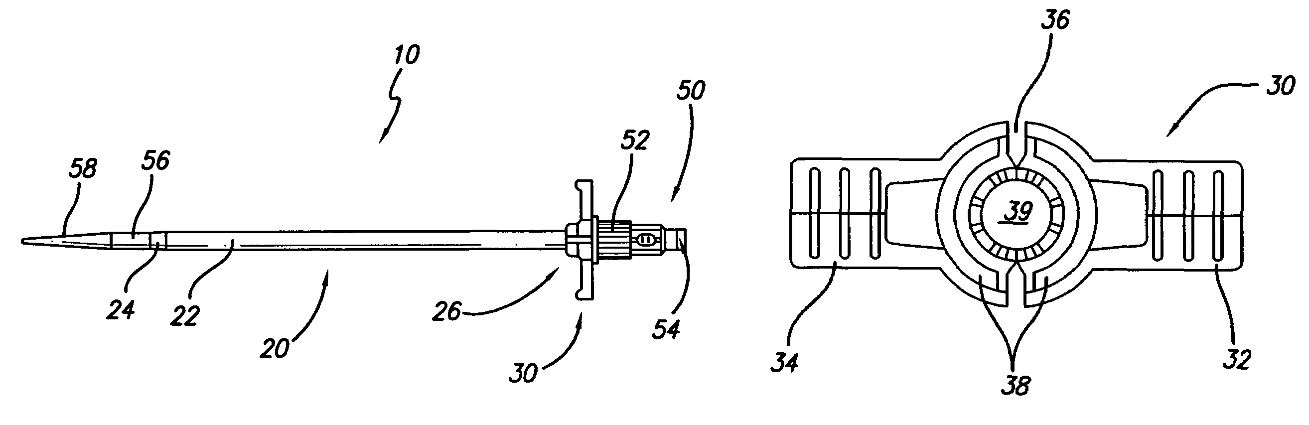
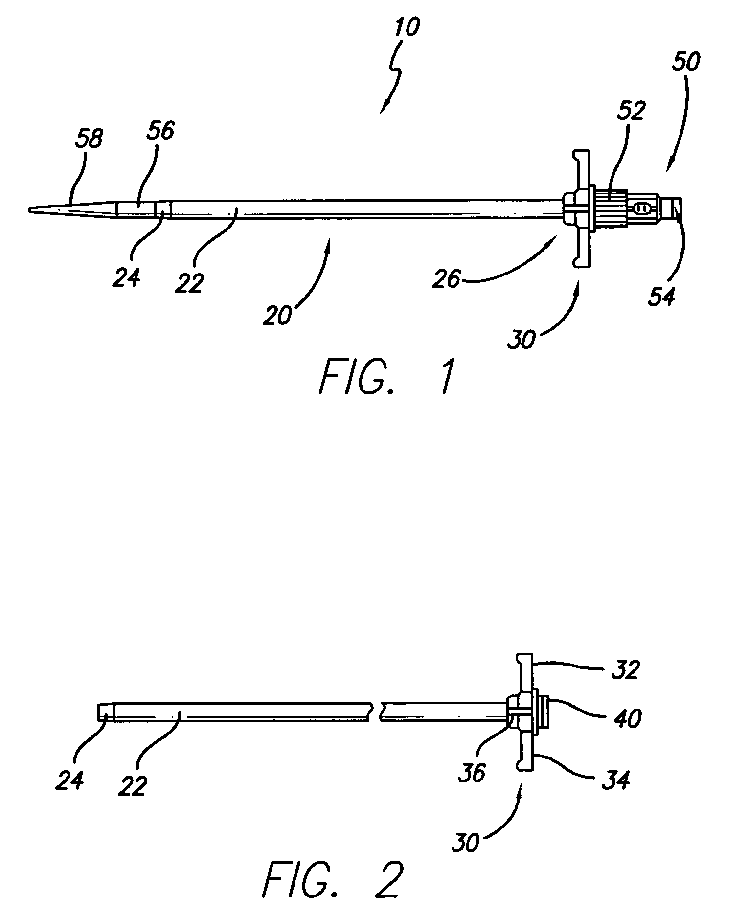
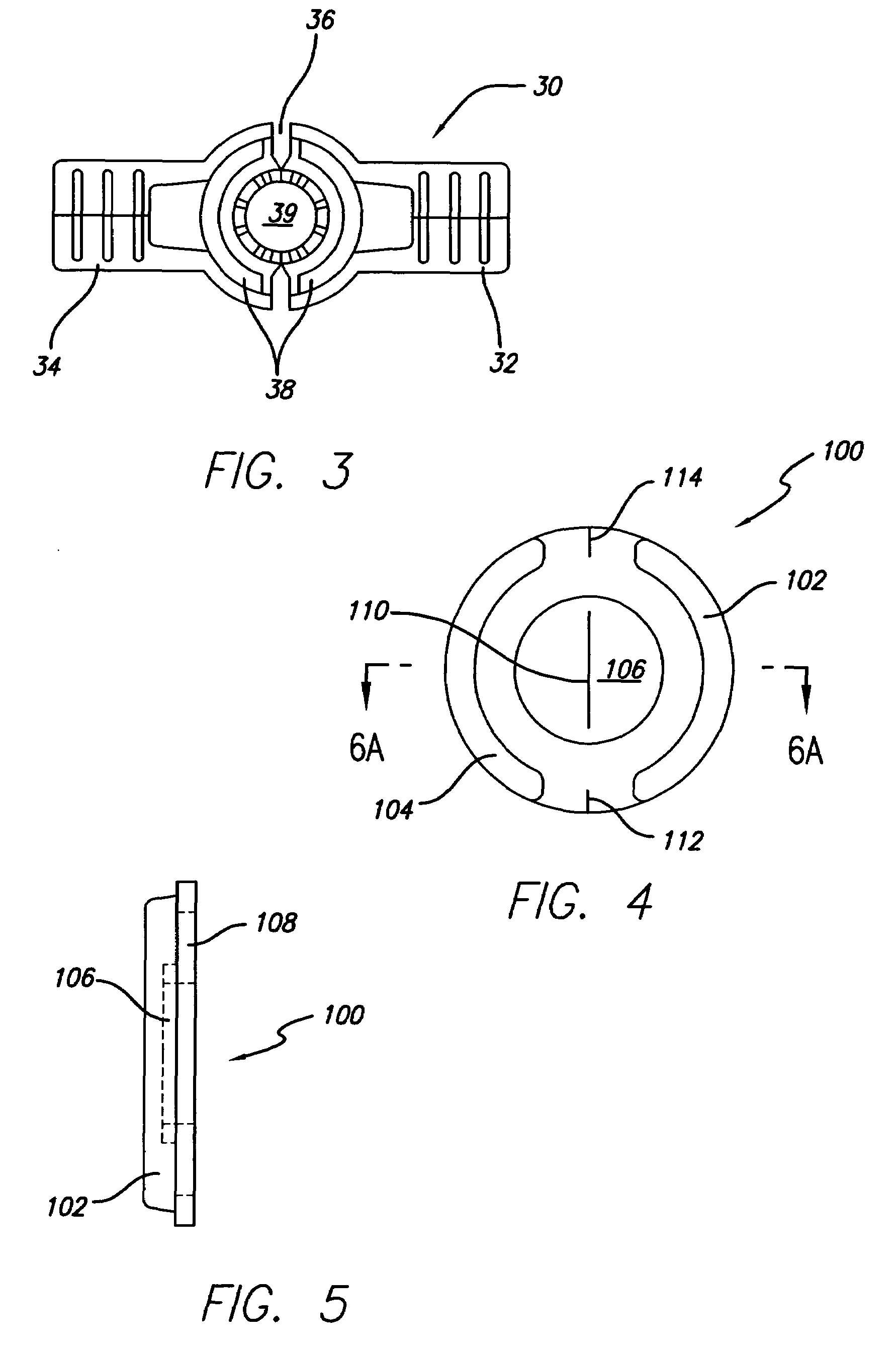
[0025]The present invention involves valves and valved sheath introducers used particularly in venous cannulation procedures. However, it should be appreciated that while the designs described herein are intended for such use, they may be equally suitable for a variety of other uses (e.g., arterial cannulati...


PUM

PropertyMeasurementUnit
angleaaaaaaaaaa
angleaaaaaaaaaa
angleaaaaaaaaaa

Abstract

A valved sheath introducer for venous cannulation, including a valve, sheath, handle and cap. The valve is configured to permit safe introduction and removal of medical instruments through the sheath introducer. The valve may have one or more anchoring members and a thickened central portion through which a slit is formed. The central portion may have one or more concave surfaces and the slit can be angled with respect to the top surface of the valve. The cap is attached to the handle, compressing a portion of the valve therebetween.

Description

CROSS-REFERENCE TO RELATED APPLICATIONS[0001]This application claims the benefit of U.S. Provisional Application No. 60 / 566,896, filed Apr. 30, 2004, which is expressly incorporated by reference as if fully set forth herein.BACKGROUND OF THE INVENTION[0002]Introducer devices are commonly utilized for inserting medical devices, such as venous access catheters, into patients. Typically, such introducer devices comprise a peel-away sheath and a hub / handle assembly which is used in conjunction with a dilator assembly to access the vein of a patient, following insertion of a needle and guidewire. In particular, procedures for introducing a catheter into a blood vessel include the cut-down method and the Seldinger technique. The Seldinger technique involves first inserting a needle through the skin of a patient and into a vein to be catheterized, inserting a guidewire through the needle and into the vein, removing the needle from the guidewire and inserting the dilator and introducer shea...

Claims


Application Information

Patent Timeline
Patent Type & Authority Patents(United States)
IPC IPC(8): A61M5/178A61B17/34A61F11/00A61M25/06A61M39/06
CPCA61B17/3415A61M39/0693A61B17/3498A61M25/0662Y10T29/49826Y10T29/49412Y10T29/49405
Inventor CHRISTENSEN, MARK A.SMITH, STEVEN M.SHANG, WALTERBEAL, JAMES D.
Owner CR BARD INC
Why Eureka
Try Eureka