Radio frequency amplifier circuit and mobile communication terminal using the same

a technology of frequency amplifier and mobile communication terminal, which is applied in the direction of high frequency amplifier, automatic tone/bandwidth control, gain control, etc., can solve the problems of high precision power supply, increase the consumption of current in a normal mode, and increase the current consumption. , to achieve the effect of simple and reduced-scale configuration and enhanced flexibility

Active Publication Date: 2009-12-29
PANASONIC SEMICON SOLUTIONS CO LTD
View PDF7 Cites 8 Cited by
  • Summary
  • Abstract
  • Description
  • Claims
  • Application Information

AI Technical Summary

Benefits of technology

[0023]Therefore, an object of the present invention is to provide a radio frequency amplifier circuit which allows increase of a setting range in which a control voltage is set for a bias current, allows a bias circuit for controlling the bias current to be configured with enhanced flexibility, and is applicable to multiple communication systems in a simple and reduced-scale configuration, and a mobile communication terminal using the radio frequency amplifier circuit.
[0033]According to the present invention, the control voltage which has values changing within an increased setting range of values is used so as to change a current flowing through the bias circuit, thereby controlling the bias current of the amplifier. Thus, it is unnecessary to provide a high precision A / D converter, thereby reducing the circuit scale of the radio frequency circuit block. Further, the configuration of the bias circuit is partially changed in accordance with the control logic for switching between the high power output operation and the low power output operation, and therefore the control signal can be reversed without addition of a logic circuit, thereby reducing the circuit scale of the radio frequency circuit block. Moreover, the increased number of amplifiers are connected to each other such that, when the power gain is increased by controlling the bias current of the amplifier, the bias circuits supply, to the respective corresponding amplifiers, the bias currents which change so as to be inversely proportional to each other. Therefore, the change of the power gain in accordance with the control voltage can be suppressed.

Problems solved by technology

Therefore, consumption of current is increased in a normal mode used for the sound communication which is more frequently used than the high speed data communication.
Further, diversified applications of the mobile communication terminal complicates a processing circuit, thereby increasing the consumption of current.
However, the HBT is disadvantageous in that the HBT requires a bias circuit for compensating temperature dependency and power supply voltage dependency.
However, the conventional radio frequency amplifier circuit as described above has the following problems.
The first problem is that it is necessary to provide a high precision power supply for the power supply voltage Vdc and a high precision power supply for the reference voltage Vref.
The second problem is that the amplifier 100 capable of changing between the high power output operation and the low power output operation requires an increased circuit scale.
The third problem is that a power gain of the radio frequency amplifier circuit is different between when the amplifier 100 performs the high power output operation and when the amplifier 100 performs the low power output operation.
In general, in the radio frequency amplifier circuit using a transistor, increase in operating current leads to increase in power gain.
Therefore, the power gain changes for each operation, and therefore a control parameter is required to have the increased number of values in the radio frequency circuit block of the mobile communication terminal, thereby complicating the control circuit.

Method used


Image

  • Radio frequency amplifier circuit and mobile communication terminal using the same
  • Radio frequency amplifier circuit and mobile communication terminal using the same
  • Radio frequency amplifier circuit and mobile communication terminal using the same

Examples


first embodiment

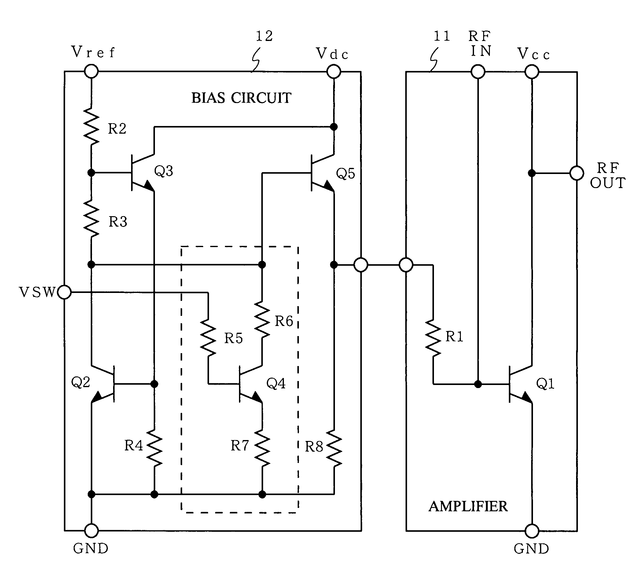
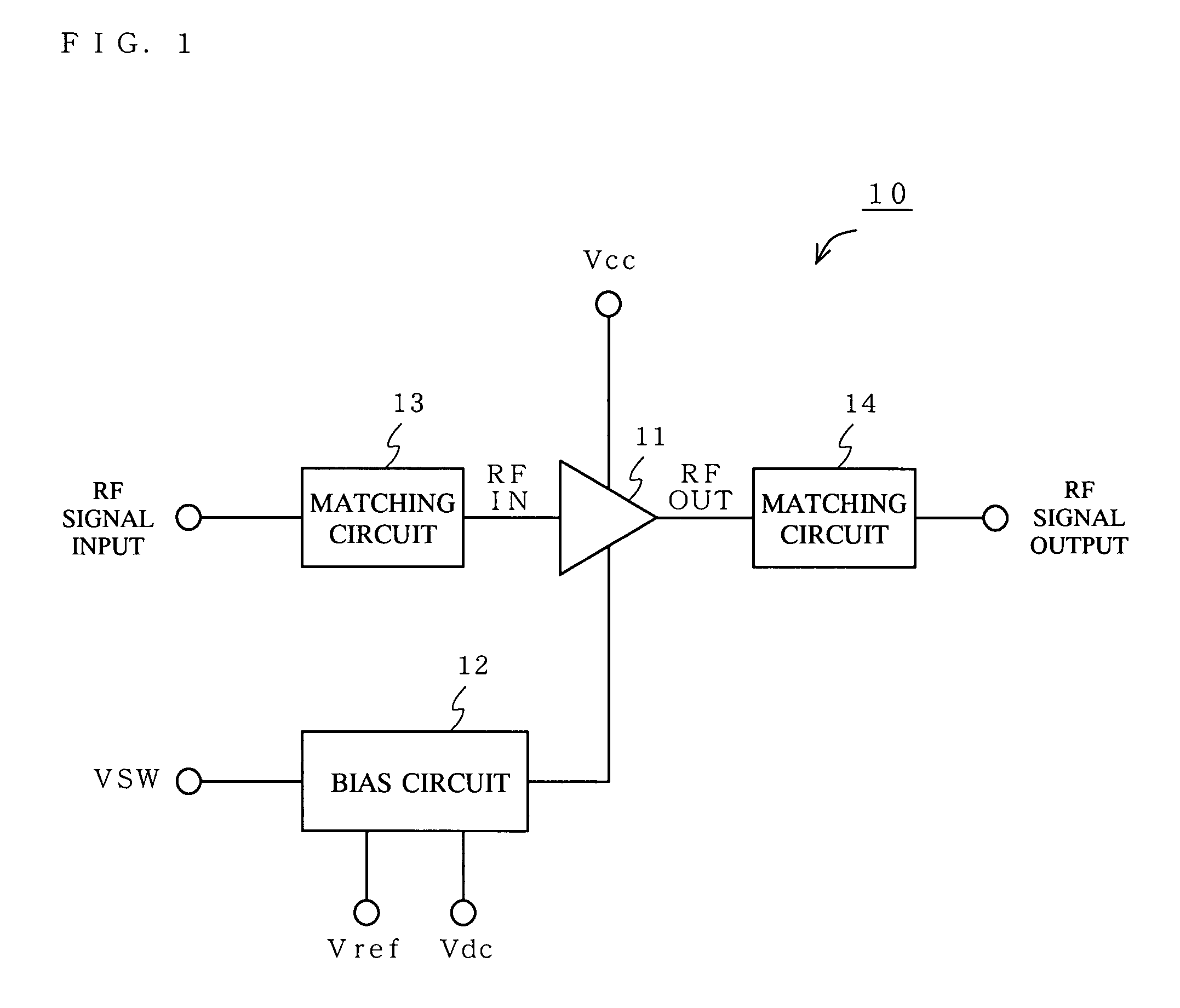
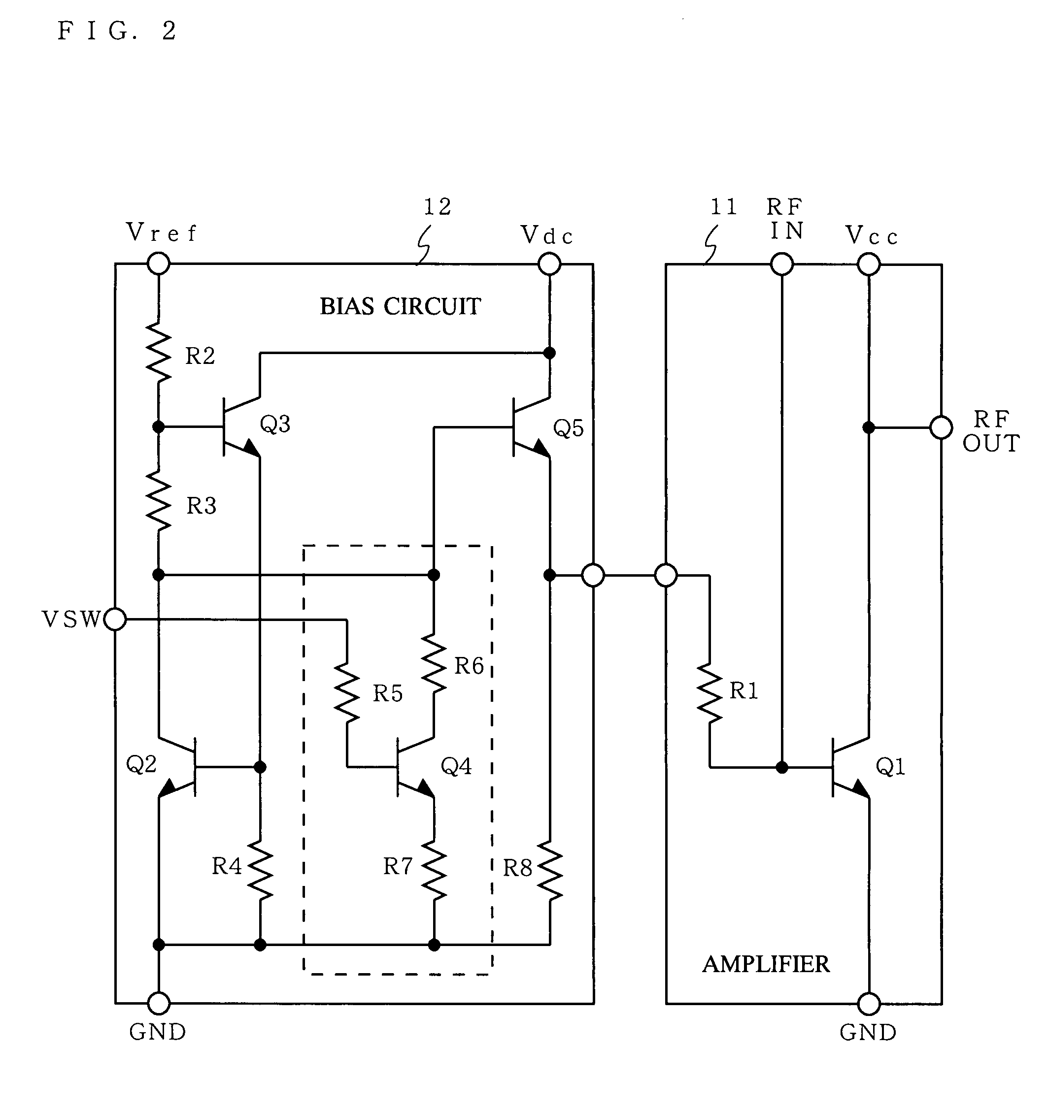
[0056]FIG. 1 is a block diagram illustrating a configuration of a radio frequency amplifier circuit 10 according to a first embodiment of the present invention. FIG. 2 is a diagram illustrating in detail a circuit configuration of an amplifier 11 and a bias circuit 12 of the radio frequency amplifier circuit 10. FIG. 3 is a block diagram illustrating a configuration of a radio communication section of a mobile telephone terminal including the radio frequency amplifier circuit 10.

[0057]Firstly, the radio communication section of the mobile telephone terminal shown in FIG. 3 will be described in detail. Thereafter, the radio frequency amplifier circuit 10 will be described in detail. The mobile telephone terminal according to the present embodiment is applicable to multiple communication systems of the W-CDMA system.

[0058]As shown in FIG. 3, the radio communication section of the mobile telephone terminal includes: a transmission section 120; a reception section 140; a synthesizer sec...

second embodiment

[0078]FIG. 8 is a diagram illustrating in detail a circuit configuration of the amplifier 11 and a bias circuit 22 of the radio frequency amplifier circuit 20 according to a second embodiment of the present invention. The radio frequency amplifier circuit 20 according to the second embodiment has the same configuration as the radio frequency amplifier circuit 10 according to the first embodiment except that the bias circuit 22 is used, in the radio frequency amplifier circuit 20, instead of the bias circuit 12. Therefore, FIG. 1 is also used as a block diagram illustrating the configuration of the radio frequency amplifier circuit 20, and a block diagram and description are not additionally provided for the radio frequency amplifier circuit 20. In the second embodiment, the radio frequency amplifier circuit 20 is used as the high power radio frequency amplifier circuit 124. Therefore, FIG. 3 is a block diagram also illustrating a configuration of a radio communication section of a m...

third embodiment

[0086]FIG. 10 is a block diagram illustrating a configuration of a radio frequency amplifier circuit 30 according to a third embodiment of the present invention. FIG. 11 is a diagram illustrating in detail a circuit configuration of the amplifier 11 and a bias circuit 32 of the radio frequency amplifier circuit 30. FIG. 12 is a block diagram illustrating a configuration of a radio communication section of a mobile telephone terminal including the radio frequency amplifier circuit 30.

[0087]Firstly, the radio communication section of the mobile telephone terminal shown in FIG. 12 will be described. Thereafter, the radio frequency amplifier circuit 30 will be described in detail. The radio communication section of the mobile telephone terminal shown in FIG. 12 has the same structure as the radio communication section of the mobile telephone terminal shown in FIG. 3 except that the transmission control circuit 170 is provided, in the radio communication section including the radio frequ...


PUM


Abstract

A bias circuit 12 includes: a transistor Q5 operable to supply, to an amplifier 11, a bias current in accordance with a base current supplied thereto; a transistor Q3 operable to pass a current in accordance with a reference voltage Vref; a transistor Q2 operable to correct, in accordance with the current passed by the transistor Q3, the base current to be supplied to the transistor Q5, so as to compensate a temperature characteristic represented by the transistor Q5; and a bias changing section (of a transistor Q4, and resistances R5, R6, and R7), connected to a base of the transistor Q5, operable to change, in accordance with a control voltage VSW, an amount of the base current to be supplied to the transistor Q5. The amplifier 11 amplifies, by using the bias current supplied by the bias circuit 12, a radio frequency signal having been inputted thereto.

Description

BACKGROUND OF THE INVENTION[0001]1. Field of the Invention[0002]The present invention relates to a radio frequency amplifier circuit for amplifying a radio frequency signal used by a transmission section of a mobile communication terminal such as a mobile telephone, and a mobile communication terminal using the radio frequency amplifier circuit, and more particularly, to a technique of controlling a bias current (output power) of the radio frequency amplifier circuit by using a control signal.[0003]2. Description of the Background Art[0004]Recently, in a mobile communication field, not only sound communication function but also data communication function of distributing an image and music has been developed. Therefore, a mobile communication terminal having an enhanced data communication function becomes predominant. For example, as the W-CDMA (Wideband Code Division Multiple Access) system, the HSDPA (High Speed Downlink Packet Access) system and the HSUPA (High Speed Uplink Packe...

Claims


Application Information

Patent Timeline
Patent Type & Authority Patents(United States)
IPC IPC(8): H03G3/10
CPCH03F3/189H03F1/30
Inventor NAKAYAMA, MASAOSUGIYAMA, HIROSHIOOHASHI, KAZUHIKOYAMAMOTO, KOUKIMOTOYOSHI, KANAME
Owner PANASONIC SEMICON SOLUTIONS CO LTD
Why Eureka
Try Eureka