Automated model configuration and deployment system for equipment health monitoring

a technology of automatic model configuration and equipment health monitoring, applied in the direction of testing/monitoring control systems, process and machine control, instruments, etc., can solve the problems of not providing as much efficacy for equipment health monitoring, prone to trial and error in creating properly functioning models, and requiring significant development and deployment of equipment models, etc., to achieve a highly scalable system and ease the burden on system engineers

Active Publication Date: 2009-12-29
SMARTSIGNAL CORP
View PDF5 Cites 82 Cited by
  • Summary
  • Abstract
  • Description
  • Claims
  • Application Information

AI Technical Summary

Benefits of technology

[0008]The invention enables quick deployment of large numbers of empirical models for monitoring large fleets of assets (jet engines, automobiles or power plants, for example), which eases the burden on systems engineers that would normally set up models individually using manually intensive techniques. This results in a highly scalable system for condition based monitoring of equipment. In addition, each model and each variable of every model will have associated with it measures of performance that assess model accuracy, robustness, spillover, bias and minimum detectable shift. The measures can easily be re-calculated at any time if need be to address changes in the model due to adaptation, system changes and anything else that could effect model performance.

Problems solved by technology

While the empirical model techniques have proven to be more sensitive and more robust than traditional physics-based models, allowing even for personalized models specific to individual machines, the development and deployment of the equipment models represents significant effort.
Empirical models are not amenable to a complete and thorough elucidation of their function, and so creating properly functioning models is prone to some trial and error.
Furthermore, since they are largely data-driven, they can only provide as much efficacy for equipment health monitoring as the data allows.
It is often difficult to know ahead of time how well a data-derived model will be able to detect insipient equipment health problems, but it is also unreasonable to await a real equipment failure to see the efficacy of the model.
Currently, model-based monitoring systems require significant manual investment in model development for the reasons stated above.

Method used


Image

  • Automated model configuration and deployment system for equipment health monitoring
  • Automated model configuration and deployment system for equipment health monitoring
  • Automated model configuration and deployment system for equipment health monitoring

Examples


Embodiment Construction

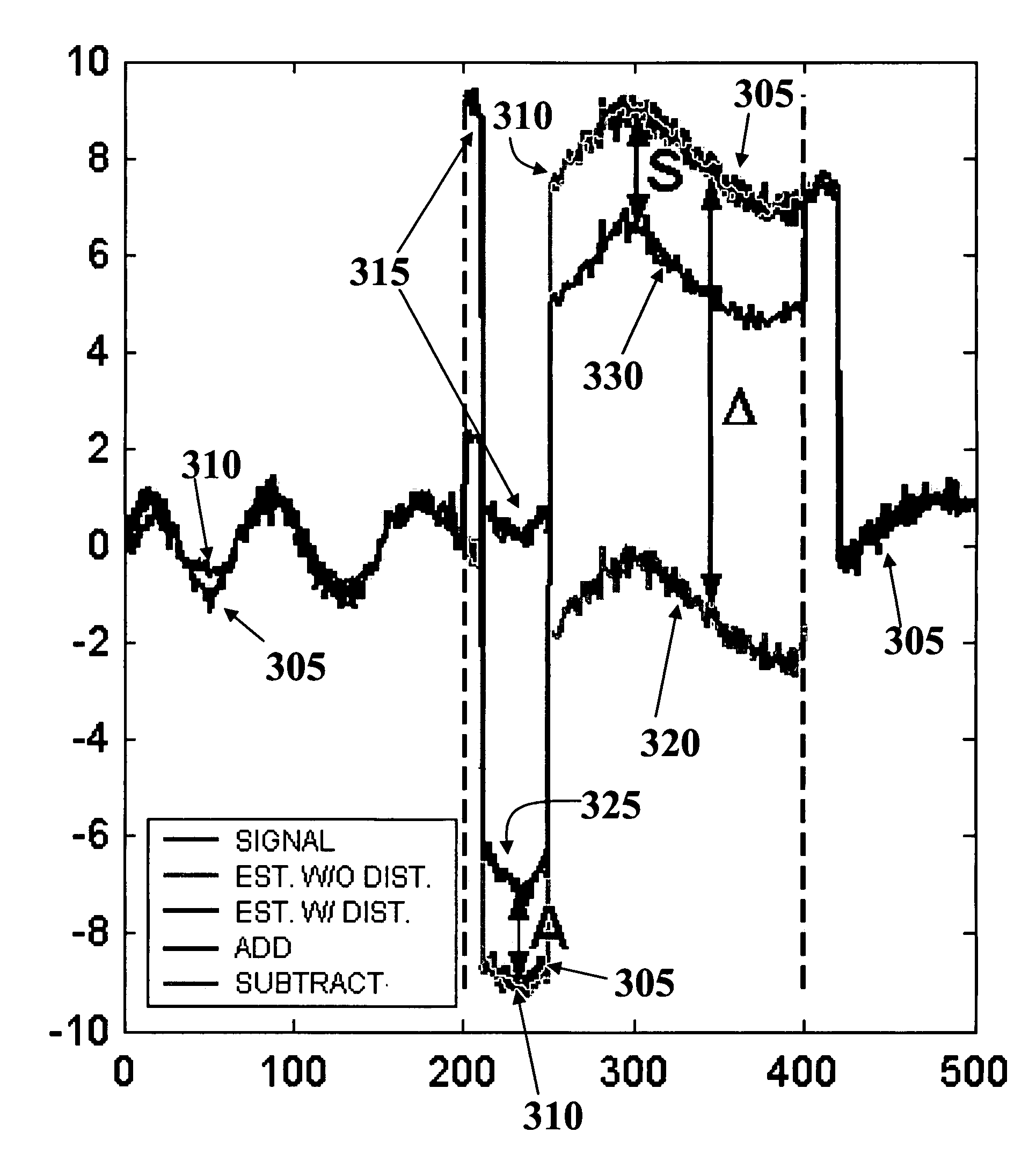
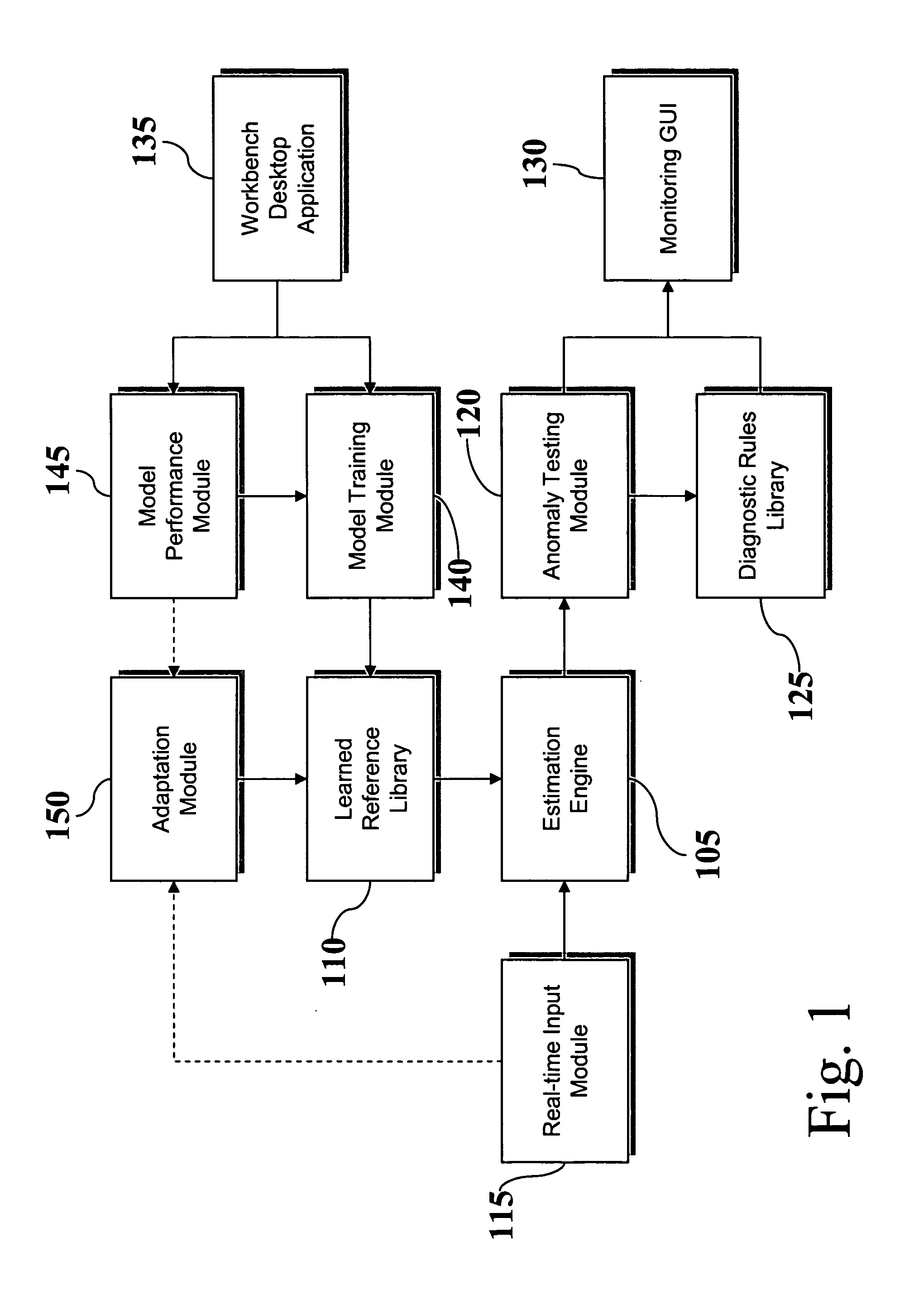
[0014]An equipment health monitoring system according to the invention is shown in FIG. 1 to comprise an estimation engine 105 at its core, which generates estimates based on a model comprising a learned reference library 110 of observations, in response to receiving a new input observation (comprising readings from multiple sensors) via real-time input module 115. An anomaly-testing module 120 compares the inputs to the estimates from estimation engine 105, and is preferably disposed to perform statistical hypothesis tests on the series of such comparisons to detect anomalies between the model prediction and the actual sensor values from a monitored piece of equipment. A diagnostic rules library 125 is provided to interpret the anomaly patterns, and both the anomaly-testing module 120 and the diagnostic rules library 125 provide informational output to a monitoring graphical user interface (GUI) 130, which alerts humans to developing equipment problems.

[0015]Separately, a workbench...


PUM


Abstract

A method for systematically configuring and deploying an empirical model used for fault detection and equipment health monitoring. The method is driven by a set of data preprocessing and model performance metrics subsystems that when applied to a raw data set, produce an optimal empirical model.

Description

CROSS-REFERENCE TO RELATED APPLICATIONS[0001]This application claims the benefit of priority under 35 U.S.C. § 119(e) to U.S. Provisional application No. 60 / 674,581 filed Apr. 25, 2005.FIELD OF THE INVENTION[0002]The present invention relates to equipment health monitoring, and more particularly to the setup and deployment of model-based equipment health monitoring systems.BACKGROUND OF THE INVENTION[0003]Recently, new techniques have been commercialized to provide equipment health monitoring and early warning of equipment failure. Unlike prior techniques that depend on a precise physical understanding of the mechanics of the machine's design, these new techniques rely on empirical modeling methods to “learn” normal equipment behavior so as to detect nascent signs of abnormal behavior when monitoring an ailing machine or process. More specifically, such new techniques learn operational dynamics of equipment from sensor data on that equipment, and build this learning into a predictiv...

Claims


Application Information

Patent Timeline
Patent Type & Authority Patents(United States)
IPC IPC(8): G06F7/60G06F17/10
CPCG05B23/0254G05B17/02
Inventor WEGERICH, STEPHAN W.WOLOSEWICZ, ANDREXU, XIAOHERZOG, JAMES P.PIPKE, ROBERT MATTHEW
Owner SMARTSIGNAL CORP
Why Eureka
Try Eureka