Dispensing system and method with radio frequency customer identification

Inactive Publication Date: 2009-12-29
EXXONMOBIL CORP (US) +2
View PDF122 Cites 113 Cited by
  • Summary
  • Abstract
  • Description
  • Claims
  • Application Information

AI Technical Summary

Benefits of technology

[0028]A technical advantage of the invention is that it integrates easily with the user interface of existing service station equipment.
[0029]Another advantage of the invention is that it provides the customer flexibility in selecting payment methods without eliminating options available with existing payment processing systems.
[0030]Anoth

Problems solved by technology

One disadvantage of the '380 patent is that the antenna which emits the electromagnetic field is embedded in the ground near the fuel dispenser.
The installation of such an antenna (or antennas where there is more than one dispenser) can be costly and can create a fire hazard from fueling spills or leaks from the fuel storage tanks typically located under ground near the fuel dispensers.
Furthermore, where multiple dispensers are present and therefore multiple antennas and controllers are present, the system does not adequately prevent a vehicle card from being activated by more than one antenna at a time and detected by more than one controller at a time, such as may happen where antennas are positioned near each other and therefore interfere with one another.
Furthermore, the system does not prevent the inadvertent detection of vehicle cards not intended to be used in a fueling transaction.
The fuel dispensing system application, however, is not desirable because maintenance of the fuel dispensing nozzle with the transceiver can present a service problem as well as a replacement problem and, furthermore, the location of the transponder and transceiver can create a fire hazard.
Application of the above-described radio frequency customer identification (RF-CID) technology to a service station environment is

Method used


Image

  • Dispensing system and method with radio frequency customer identification
  • Dispensing system and method with radio frequency customer identification
  • Dispensing system and method with radio frequency customer identification

Examples


Embodiment Construction

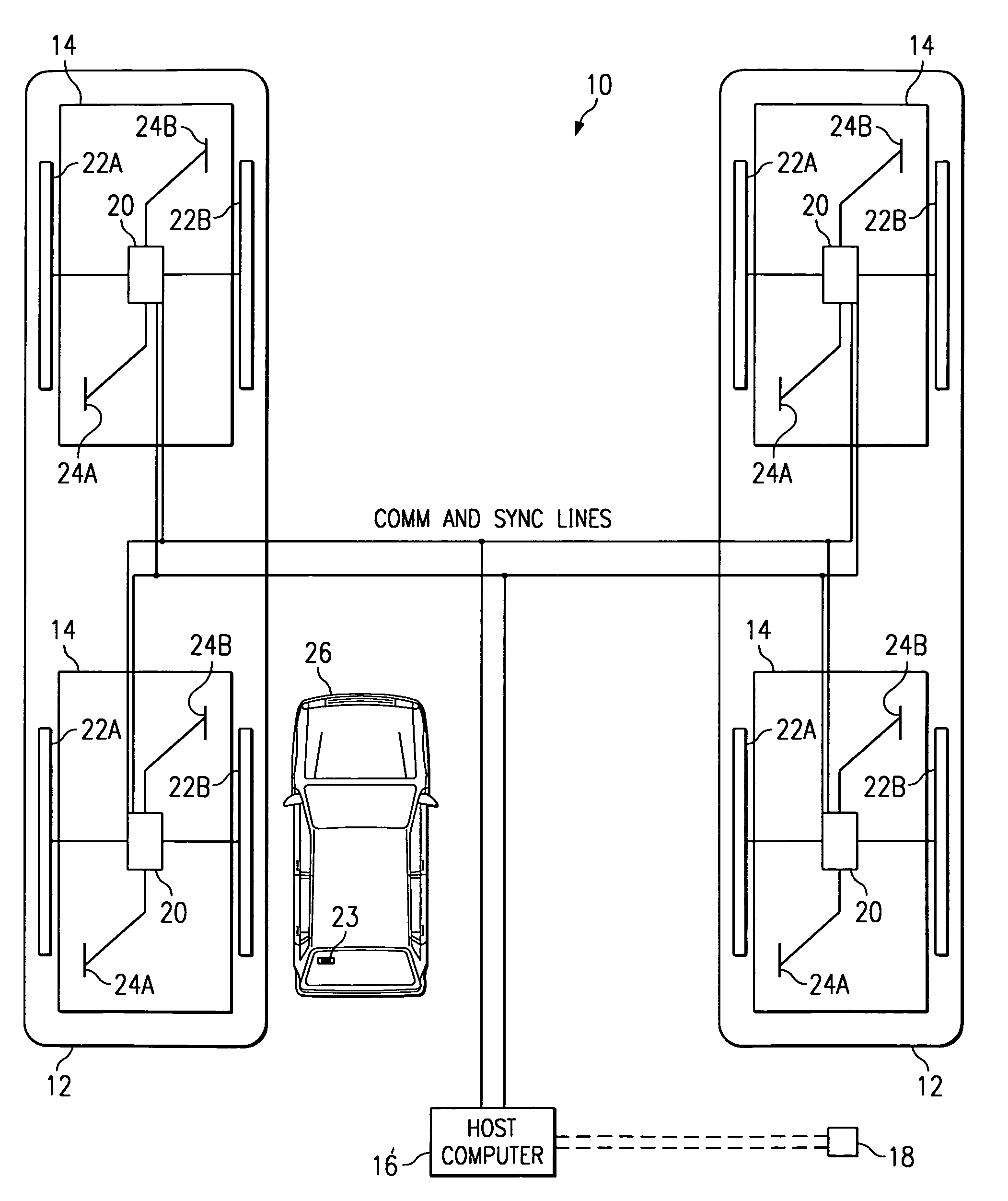
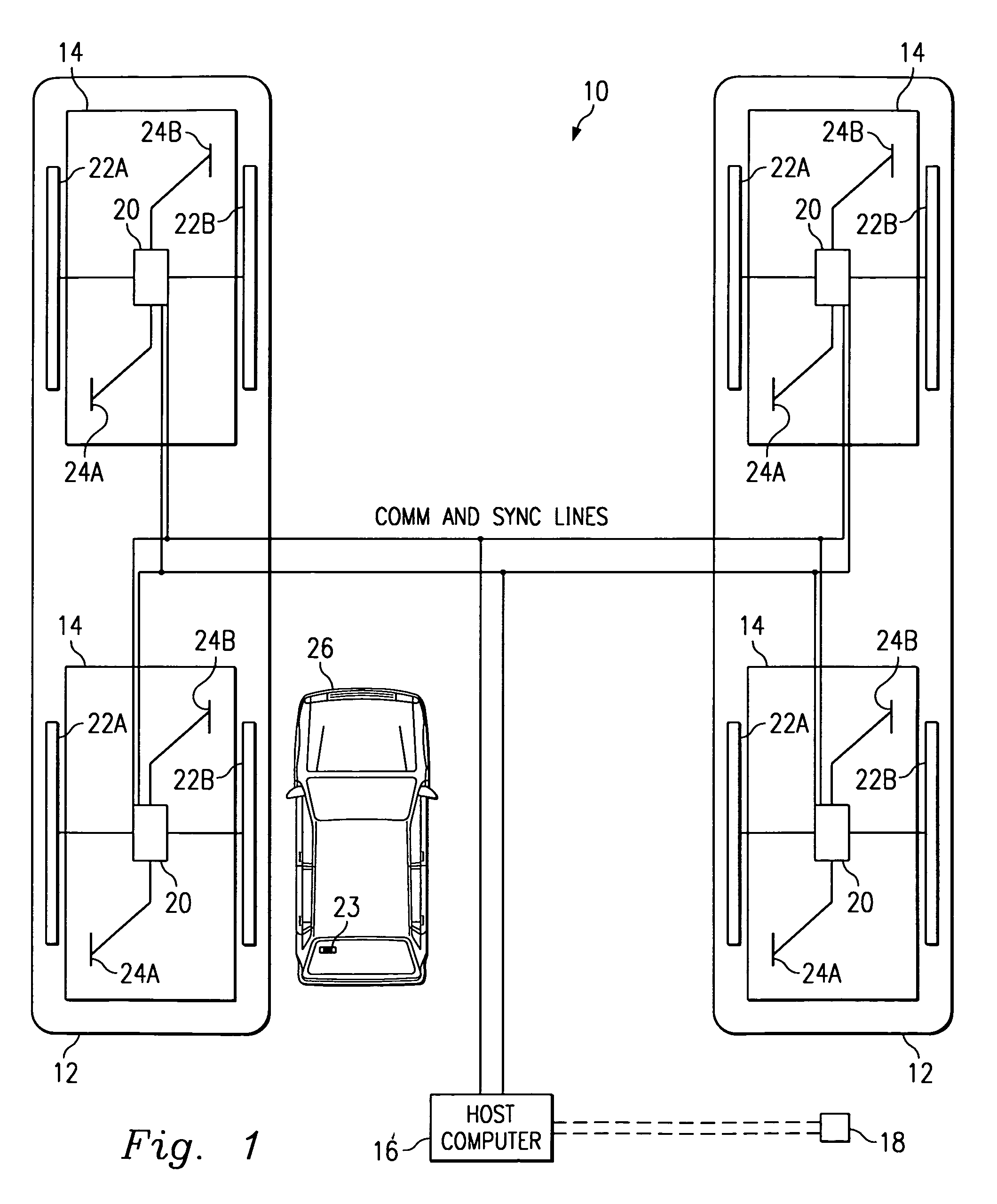
[0052]In FIG. 1, the reference numeral 10 refers to a customer identification (CID) system embodying features of the present invention. The system 10 electronically identifies a customer, authorizing a transaction involving the purchase of goods or services by that customer, and subsequently bills the customer's account for the services. In one embodiment the system 10 identifies, authorizes, and bills customers for services provided at a service station. Generally, the system 10 allows customers to drive up to a fuel dispenser and immediately begin pumping fuel (or have fuel pumped for them) without having to go inside the service station building to pay for the fuel or having to insert a credit card into a card reader at the fuel dispenser. As explained further below, the system 10 may also be used for other services at the station such as a car wash or for making payments inside a convenience store.

I. System Overview

[0053]In one embodiment (FIG. 1), the system 10 is implemented i...


PUM


Abstract

A system and method for providing a fuel dispenser with radio frequency customer identification capabilities. The system and method determines whether a transponder containing customer identification data is within range of a dispenser, the dispenser requiring activation by the customer to initiate a transaction and including a reader associated therewith for emitting radio frequency signals within the dispenser range, and for receiving customer identification data from the transponder responsive to the emitted radio frequency signals received by the transponder. When the transponder is within range of the dispenser, an in-range indication is provided to the customer. A determination is made whether the dispenser has been activated by the customer following a determination that the transponder is within the dispenser range. Upon activation of the dispenser following the determination that the transponder is within the dispenser range, the customer identification data received by the reader is associated with a transaction at the activated dispenser, whereupon the transaction at the activated dispenser is permitted and charged to the customer according to the customer identification data. The system easily retrofits onto an existing, conventional fuel dispenser.

Description

CROSS REFERENCE[0001]This application is a continuation-in-part of U.S. patent application Ser. No. 08 / 768,723, filed on Dec. 18, 1996 now abandoned, which claims the benefit of U.S. Provisional Application No. 60 / 009,369, filed Dec. 29, 1995.BACKGROUND OF THE INVENTION[0002]The present invention relates to dispensers and, more particularly, to fuel dispensers that uses radio frequency identification technology to automatically identify a customer with little or no customer interaction in order to authorize the sale of products or services to the customer and to subsequently bill the customer's charge account for the products or services. The present invention is particularly useful in a service station environment where customers may purchase fuel for their vehicles, obtain a car wash, or purchase other items such as food, drinks, or sundries from a convenience store, or drive-through window, that may be located on the premises.[0003]Typically, when a customer purchases fuel at a s...

Claims


Application Information

Patent Timeline
IPC IPC(8): G06Q40/00
CPCG06Q20/208G06Q20/3278G07G1/009G07F13/025G07G1/0036G06Q30/06G06Q20/321
Inventor GIORDANO, JOSEPH AUGUSTHENDRICKS, SAMUEL S.JACOBS, CARL R.MAYS, THOMAS L.MCCALL, DON CHARLESNADKARNI, GEETA BHOLANATHGUTHRIE, KAREN SCOTTSARGENT, LLOYD G.TURNER, JEFFREY L.WILKINS, DEBORAH T.BARINK, BERNARDFLAXL, THOMAS JOSEFHAGL, ANDREASHOLODAK, GEORGE A.D'HONT, LOEKLARSON, SCOTT D.LORENTZEN, ROBERT A.PEARSON, JOSEPHTIP, ANNEWEYER, ALEX J.
Owner EXXONMOBIL CORP (US)
Why Eureka
Try Eureka