Variable valve operating device

a variable valve and operating device technology, applied in valve drives, machines/engines, mechanical equipment, etc., can solve the problems of increasing the diameter of the roller and enlarge the size of the variable valve operating device, and unable to achieve adequate durability, etc., to inhibit the coupling shaft from bending

Inactive Publication Date: 2010-01-05
TOYOTA JIDOSHA KK
View PDF17 Cites 7 Cited by
  • Summary
  • Abstract
  • Description
  • Claims
  • Application Information

AI Technical Summary

Benefits of technology

[0015]When the variable valve operating device described in Japanese Patent Laid-open No. 2003-239712 is used, the valve cam transmits a driving force to the swing cam via the first and second rollers. When, as described above, a roller is used as a member that comes into contact with the valve cam, and another roller is used as a member that comes into contact with the swing cam, it is possible to reduce friction prevailing during driving force transmission and improve the fuel efficiency of an internal combustion engine.
[0017]The present invention has been made to solve the above problem. It is an object of the present invention to provide a compact, highly durable variable valve operating device that is capable of inhibiting friction that may arise during driving force transmission.
[0019]When, in the first aspect of the present invention, the camshaft rotates, its rotary motion is transmitted from the drive cam to the first roller and conveyed to the slide surface of the swing member via the second roller, which is coaxial with the first roller. In this instance, contact surface pressure is exerted between the first roller and the cam surface of the drive cam and between the second roller and the slide surface. However, the contact surface pressure between the first roller and the cam surface of the drive cam is reduced because the first roller has a larger diameter than the second roller. The contact surface pressure between the second roller and the slide surface is reduced because the slide surface is curved toward the drive cam surface. Further, since the second roller, which comes into contact with the slide surface, has a smaller diameter than the first roller, an increase in the distance between the slide surface and the cam surface of the drive cam is inhibited. Therefore, the first aspect of the present invention not only provides increased durability due to a decrease in the contact surface pressure, but also makes the whole variable valve operating device compact.
[0021]According to the second aspect of the present invention, the driving force, which is input from the drive cam to the first roller, and the reaction force, which is input from the slide surface of the swing member to the second rollers on both sides, balance at the center of the coupling shaft. Therefore, it is possible to inhibit the coupling shaft from bending.
[0025]According to the fourth aspect of the present invention, the driving force, which is input from the cam surface of the drive cam to the first rollers on both sides, and the reaction force, which is input from the slide surface to the second roller at the center, balance at the center of the coupling shaft. Therefore, it is possible to inhibit the coupling shaft from bending.

Problems solved by technology

Therefore, adequate durability might not be obtained depending on the materials and shapes of the members.
As a result, an increase in the roller diameter enlarges the size of the variable valve operating device.

Method used


Image

  • Variable valve operating device
  • Variable valve operating device
  • Variable valve operating device

Examples


Embodiment Construction

[0034]An embodiment of the present invention will now be described with reference to FIGS. 1 to 7.

[Configuration of Variable Valve Operating Device According to Present Embodiment]

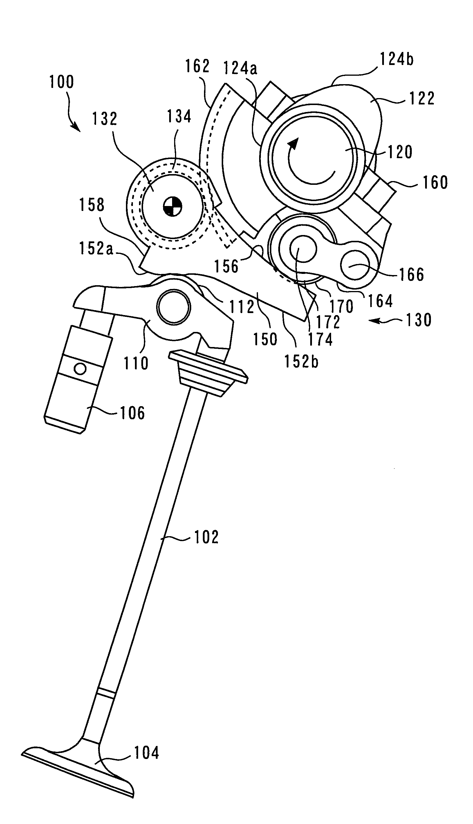
[0035]FIG. 1 is a side view illustrating the configuration of a variable valve operating device 100 according to an embodiment of the present invention. The variable valve operating device 100 includes a rocker arm type mechanical valve train. A drive cam 122, which is installed over a camshaft 120, converts a rotary motion of the camshaft 120 to a swing motion of a rocker arm (valve support member) 110. The swing motion of the rocker arm is then converted to a vertical reciprocating motion of a valve 104 that is supported by the rocker arm 110. The drive cam 122 has two cam surfaces 124a and 124b, which differ in profile. One cam surface, which is a nonoperating surface 124a, is formed at a fixed distance from the center of the camshaft 120. The other cam surface, which is an operating surface 124b, is fo...


PUM


Abstract

The present invention relates to a variable valve operating device and makes it possible to inhibit friction during driving force transmission and provide high durability through the use of a compact configuration.A first roller 170, which comes into contact with a drive cam surface 124 of a camshaft 120, has a larger diameter than a second roller 172, which comes into contact with a slide surface 156 of a swing member 150. A coupling shaft 174 couples the first roller 170 to the second roller 172 so that the rollers 170, 172 can rotate independently. The slide surface 156 is curved toward the drive cam surface 124.

Description

TECHNICAL FIELD[0001]The present invention relates to a variable valve operating device for an internal combustion engine, and more particularly to a variable valve operating device that is capable of mechanically changing the operating characteristic of a valve.BACKGROUND ART[0002]A conventionally known variable valve operating device that is disclosed, for instance, by Japanese Patent Laid-open No. 2003-239712 mechanically changes the valve lift amount and valve timing in accordance with the operating state of an engine. In the variable valve operating device described in Japanese Patent Laid-open No. 2003-239712, a guide arm is fastened to a control shaft, which is positioned in parallel with a camshaft. One end of a follower is installed over the guide arm and allowed to swing freely. A swing cam is installed over the control shaft and allowed to swing freely, and a rocker arm is pressed against a surface of the swing cam. A first roller and a second roller, which can rotate ind...

Claims


Application Information

Patent Timeline
Patent Type & Authority Patents(United States)
IPC IPC(8): F01L1/34
CPCF01L1/267F01L13/0063F01L1/185F01L1/2405Y10T74/2107F01L2013/0068F01L2105/02F01L2305/02
Inventor TATENO, MANABUEZAKI, SHUICHIASADA, TOSHIAKI
Owner TOYOTA JIDOSHA KK
Why Eureka
Try Eureka