
Power generation control apparatus for hybrid vehicle

Active Publication Date: 2014-12-11
TOYOTA JIDOSHA KK
View PDF7 Cites 7 Cited by
  • Summary
  • Abstract
  • Description
  • Claims
  • Application Information

AI Technical Summary

Benefits of technology

This patent describes a power generation control system for vehicles that increases power generation and fuel efficiency by using the internal combustion engine and a motor to provide torque during certain operational modes. The system also adjusts the output torque of the internal combustion engine to improve thermal efficiency and prevent excessive battery charging. Overall, this system enables vehicles to generate more power while reducing fuel consumption and improving overall energy efficiency.

Problems solved by technology

However, Patent Document 1 neither discloses nor even mentions control for improving the thermal efficiency of the internal combustion engine while regenerative power generation is underway.
During an idling operation, substantially no torque is output from the internal combustion engine, and therefore the thermal efficiency of the internal combustion engine is low.

Method used


Image

  • Power generation control apparatus for hybrid vehicle
  • Power generation control apparatus for hybrid vehicle
  • Power generation control apparatus for hybrid vehicle

Examples


first embodiment

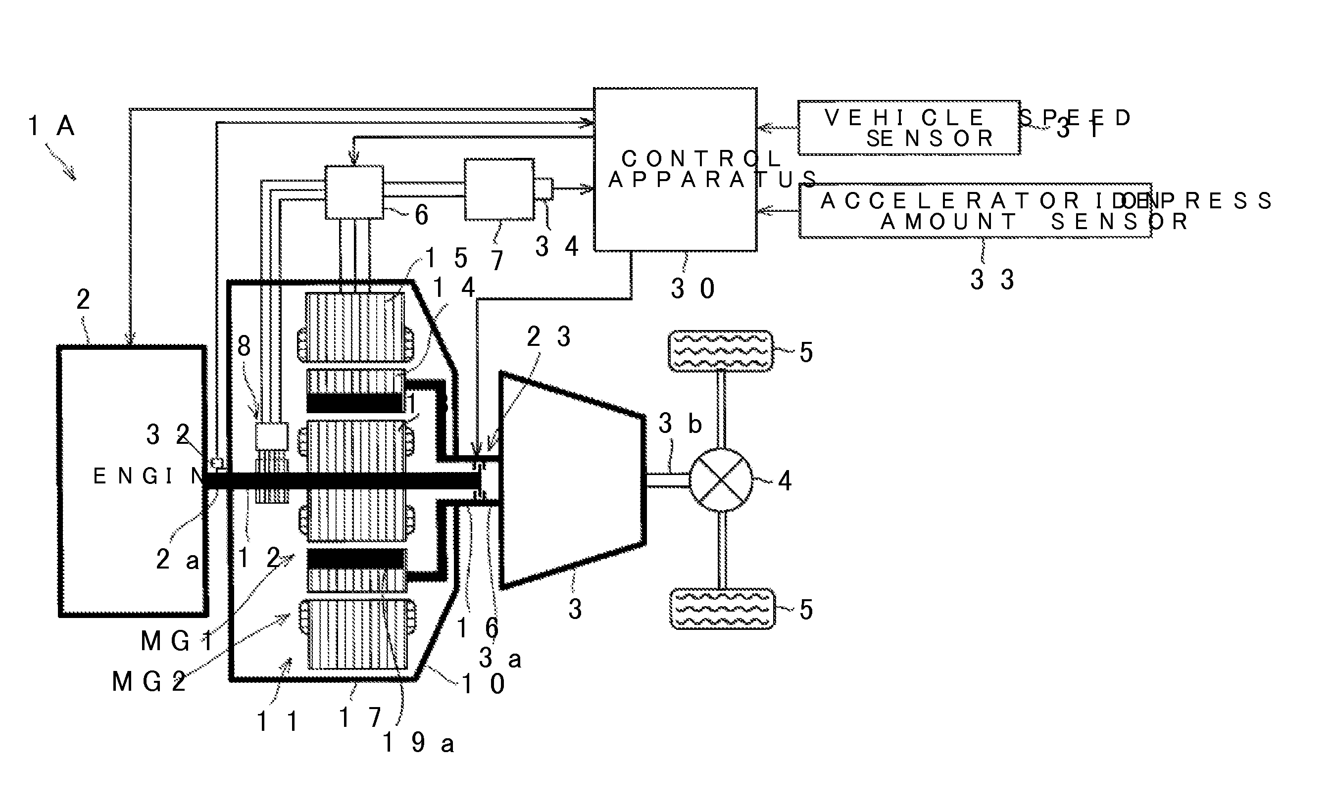
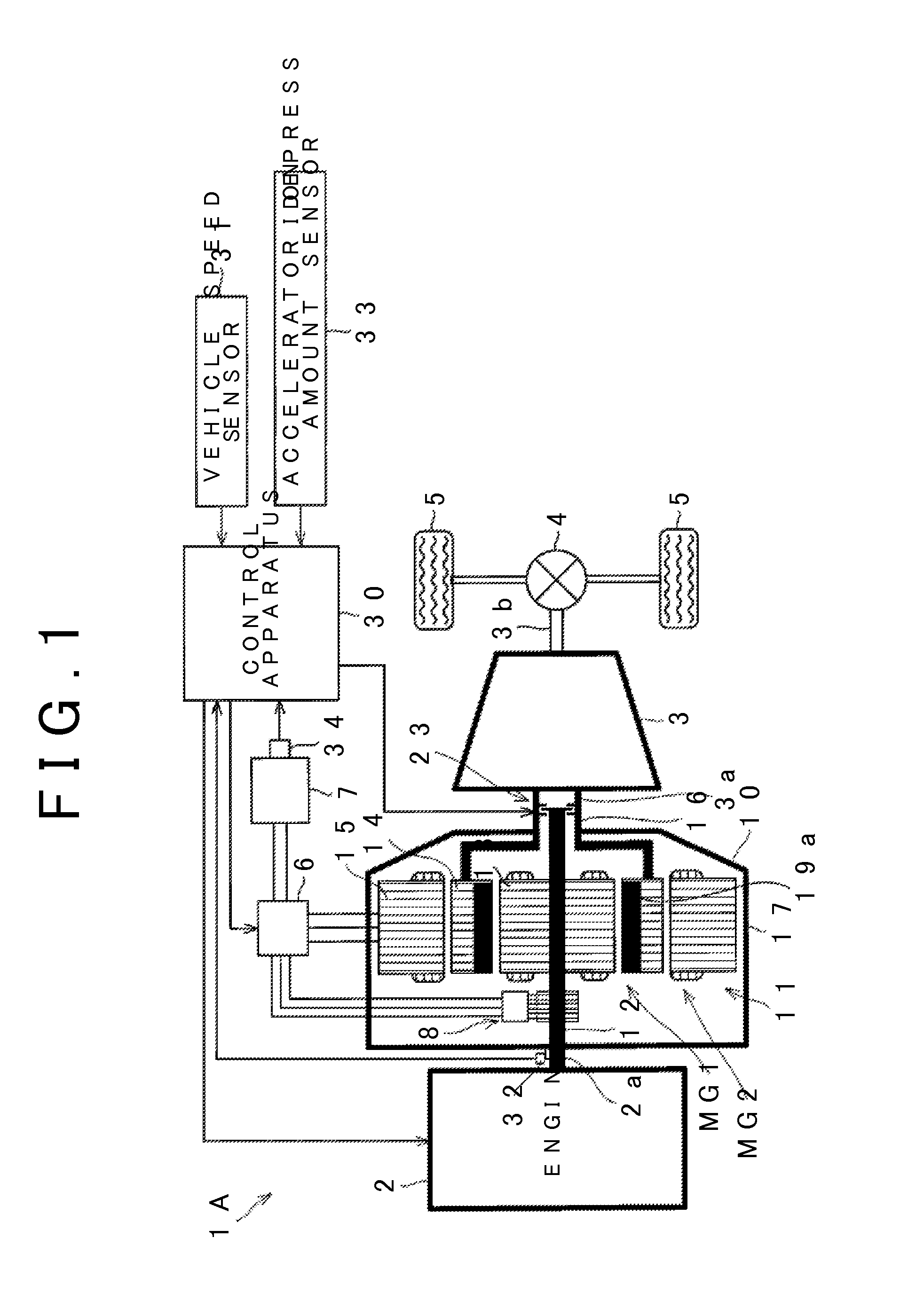
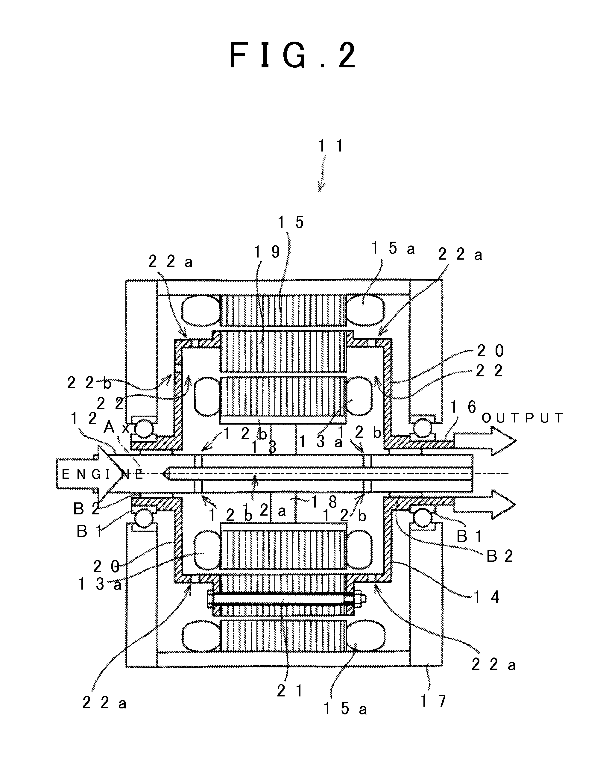
[0029]FIG. 1 is a schematic view showing a hybrid vehicle incorporating a power generation control apparatus according to a first embodiment of the invention. An internal combustion engine (also referred to hereafter as an engine) 2 is installed in a vehicle 1A as a travel power source. The engine 2 is a conventional engine installed in a vehicle such as an automobile, and therefore detailed description thereof has been omitted. Although not shown in the drawing, accessories such as a power steering and an air-conditioner are connected to an output shaft 2a of the engine 2. These accessories are driven by rotation of the output shaft 2a. A transmission 3 is also installed in the vehicle 1A. The transmission 3 is a conventional transmission configured to be capable of switching between a plurality of speed ratios differing from each other in a magnitude of a speed ratio between an input shaft 3a and an output shaft 3b. Hence, detailed description of the transmission 3 has likewise be...

second embodiment

[0063]Referring to FIGS. 7 and 8, a power generation control apparatus according to a second embodiment will be described. In this embodiment, the power generation amount increase control routine executed by the control apparatus 30 differs from the first embodiment, but in all other respects, the second embodiment is identical to the first embodiment. Likewise in this embodiment, therefore, FIG. 1 will be referred to in relation to the vehicle 1A. Furthermore, likewise in this embodiment, the control apparatus 30 executes the power generation amount increase determination routine of FIG. 4 repeatedly at predetermined period intervals while the vehicle 1A travels.

[0064]FIG. 7 shows the power generation amount increase control routine executed by the control apparatus 30 in this embodiment. Note that processes shown in FIG. 7 that are shared with the routines of FIGS. 4 and 5 have been allocated identical reference symbols, and description thereof has been omitted. This control routi...

third embodiment

[0070]Referring to FIG. 9, a power generation control apparatus according to a third embodiment will be described. In this embodiment, the power generation amount increase control routine executed by the control apparatus 30 differs from the first embodiment, but in all other respects, the third embodiment is identical to the first embodiment. Likewise in this embodiment, therefore, FIG. 1 will be referred to in relation to the vehicle 1A. Furthermore, likewise in this embodiment, the control apparatus 30 executes the power generation amount increase determination routine of FIG. 4 repeatedly at predetermined period intervals while the vehicle 1A travels.

[0071]FIG. 9 shows the power generation amount increase control routine executed by the control apparatus 30 in this embodiment. Note that processes shown in FIG. 9 that are shared with the routine of FIG. 4, 5, or 7 have been allocated identical reference symbols, and description thereof has been omitted. This control routine is li...


PUM


Abstract

In a power generation control apparatus applied to a hybrid vehicle including a compound motor in which a wound rotor is connected to an internal combustion engine and a magnet rotor is connected to a transmission, when regenerative power generation is underway and the internal combustion engine is operative, a first motor / generator constituted by the wound rotor and the magnet rotor and the internal combustion engine are controlled such that torque output from the internal combustion engine is increased by torque applied to the internal combustion engine from the first motor / generator, and a power generation amount of a second motor / generator constituted by the magnet rotor and a stator is increased such that torque transmitted to an output shaft from the internal combustion engine is not applied to a drive wheel.

Description

TECHNICAL FIELD[0001]The invention relates to a power generation control apparatus that is applied to a hybrid vehicle including: an internal combustion engine; an output member to which torque output from the internal combustion engine is transmitted and which is connected to a drive wheel to be capable of power transmission; a motor provided to be capable of applying torque output thereby to the internal combustion engine; and a generator connected to the output member.BACKGROUND ART[0002]A conventional hybrid vehicle includes a power distribution planetary gear mechanism having a sun gear, a carrier, and a ring gear to which a first motor / generator, an internal combustion engine, and a reduction mechanism that outputs power to a drive wheel are respectively connected, and a second motor / generator capable of outputting power to the ring gear of the planetary gear mechanism. A conventional control apparatus for this type of hybrid vehicle performs acceleration travel, in which the ...

Claims


Application Information

Patent Timeline
IPC IPC(8): B60W20/00B60W10/08B60W10/06B60L50/15B60L50/16
CPCB60W20/108Y10S903/93B60W10/08B60W10/06B60L7/14B60W20/13B60W20/15B60K6/448B60K6/547B60L15/2009B60L50/61B60L50/16B60L2220/52B60L2240/423B60L2240/421B60L2240/441B60L2240/443Y02T10/70Y02T10/62Y02T10/64Y02T10/7072F02D29/02F02D29/06Y02T10/72
Inventor FUJIYOSHI, TADASHISHIINA, TAKAHIROMURAKAMI, AKIRAMIYANO, TATSUYAWATANABE, TAKAOHIBINO, RYOICHI
Owner TOYOTA JIDOSHA KK
Learn More