Turbo vortex piston

a technology of vortex piston and piston head, which is applied in the direction of pistons, combustion engines, machines/engines, etc., can solve the problems of lowering the producible power of the engine, no power production, and premature combustion of the air/fuel mixtur

Inactive Publication Date: 2015-09-17
MORGAN KENNETH HOWARD
View PDF3 Cites 7 Cited by
  • Summary
  • Abstract
  • Description
  • Claims
  • Application Information

AI Technical Summary

Problems solved by technology

The problem with existing designs to date is they are inefficient because they are usually flat on top or a dish that is aerodynamically foiled both in their ability to homogenize fuel and the ultimate problematic deficiency that results in detonation or premature combustion of the air / fuel mixture.
This results in premature burning of the air / fuel mixture using up the fuel charge while resulting in no production of power but further that the premature ignition of the air / fuel mixture can oppose the upward stroke of the piston on the compression stroke thereby lowering the producible power of the engine when the piston finally rolls over into the power stroke.

Method used


Image

  • Turbo vortex piston
  • Turbo vortex piston
  • Turbo vortex piston

Examples


Embodiment Construction

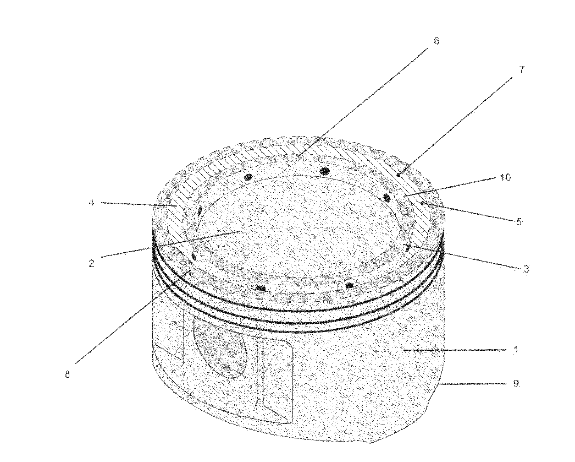
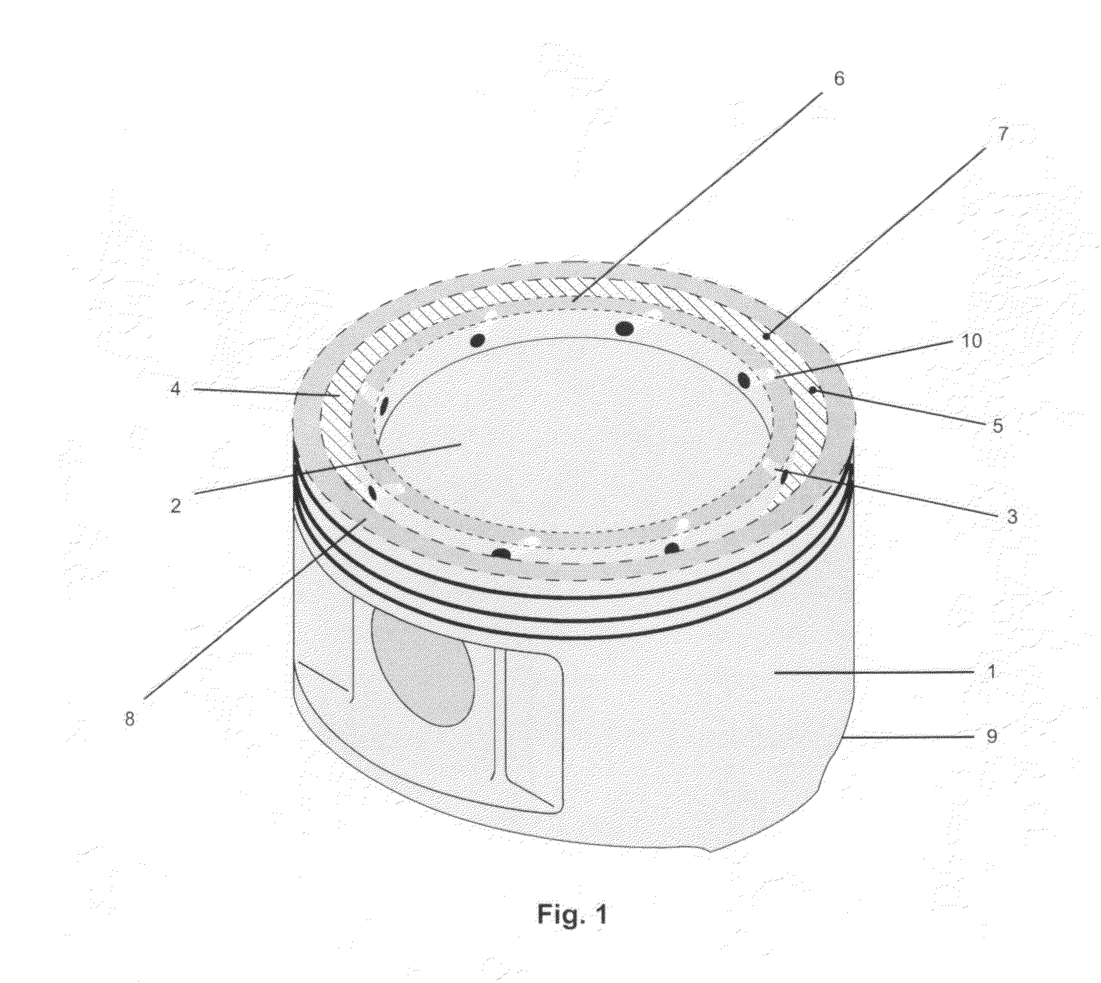
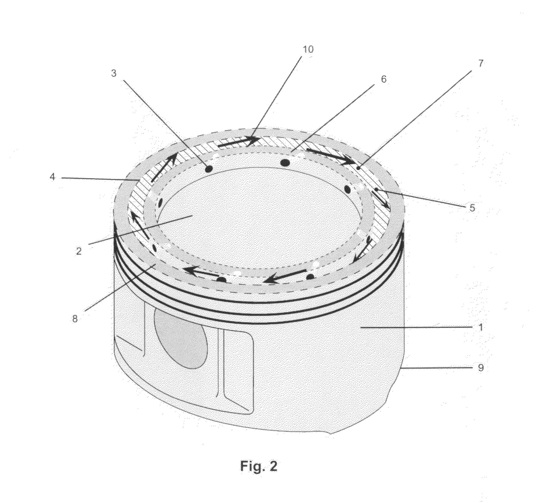
[0035]As the current embodiment of the piston 1 begins on the travel upward on the compression stroke, the air / fuel mixture while being compressed is presented to the center plenum 2 of the Piston. This air / fuel mixture is then forced through the Vortex jets 3 from the center of the Piston plenum 2 into the outer swirl chamber 4. Important here to take note, that the compression that is applied to the center plenum 2 is also applied to the whole top surface of the machined “imprint” in the piston crown which incorporates 2,3,4,6,7,8. Therefore as the air / fuel mixture that is being passed through the vortex jets 3 into the swirl chamber 4 and is contained in part by the compression pressure keeping it forced down against the piston crown 2,3,4,6,7,8 and also by the low pressure zones that occur naturally at the leading edge of each Vortex jet 7. Anytime high pressure is passing through a small orifice 3 a resultant low pressure area is created just in front of it 7.

[0036]The holes ma...


PUM


Abstract

A piston for use in 4 Cycle reciprocating Internal Combustion Engines. The one embodiment includes a multifunctional Engraving or Imprint that is machined into the crown of the piston. This “Imprint” consists of concentric circles of metal removed in a machining process resulting in the compartments of the functional areas within the crown of the piston connected by either the height and or cross drillings within the Imprint. The functional result is to create low and high pressure zones within the crown of the piston as it proceeds upward on the compression stroke facilitating the creation of an active moving rotational swirl in the outer 25% on the top surface area of the piston circumference. The active swirl pattern results in ultimate homogenization of the air fuel mixture leaving no area of the combustion chamber with weak or separated air and fuel molecules resulting in enhanced power and complete combustion.

Description

CROSS REFERENCE TO RELATED APPLICATIONS[0001]This application claims priority over U.S. Provisional Patent Application No. 61 / 802,617 filed Mar. 16, 2013 and entitled “Turbo Vortex Piston” the disclosure of which is incorporated herein in its entiretyBACKGROUND OF THE INVENTION[0002]The existing configurations of reciprocating internal combustion engines are comprised of a piston moving up and down within a cylinder or several cylinders incorporated within a block assembly. Said block has a cylinder head, which encompasses an intake and exhaust valve for the insertion of fuel and removal of the spent exhaust gases after combustion. This assembly also referred to as an internal combustion engine operates with four cycles defined as; Intake, Compression, Power and Exhaust—each function of which occurs in one-half turn increments of a rotating crankshaft that takes the movement of the pistons up and down movements and converts them to a rotation shaft making this power usable for today...

Claims


Application Information

Patent Timeline
Patent Type & Authority Applications(United States)
IPC IPC(8): F02B23/06F02F3/24F02B23/08
CPCF02B23/0627F02F3/24F02B23/08F02B2023/108F02F3/28Y02T10/12F02B3/06F02F3/00F02F3/22F05C2201/021F05C2201/0448
Inventor MORGAN, KENNETH HOWARD
Owner MORGAN KENNETH HOWARD
Why Eureka
Try Eureka