
Gas engine having a laser ignition device

a laser ignition and gas engine technology, applied in combustion engines, machines/engines, charge feed systems, etc., can solve the problems of reducing the efficiency of the internal combustion engine, high flow velocity and consequently high turbulence in the combustion chamber, and high wall heat loss, so as to achieve reliable and low-emission combustion and good efficiency

Inactive Publication Date: 2012-02-02
ROBERT BOSCH GMBH
View PDF6 Cites 7 Cited by
  • Summary
  • Abstract
  • Description
  • Claims
  • Application Information

AI Technical Summary

Benefits of technology

[0009]This makes it possible for the flame front to propagate in the form of a sphere in all directions of the chamber, significantly shortening the flame paths and the compression time. Consequently the efficiency of the internal combustion engine also increases.
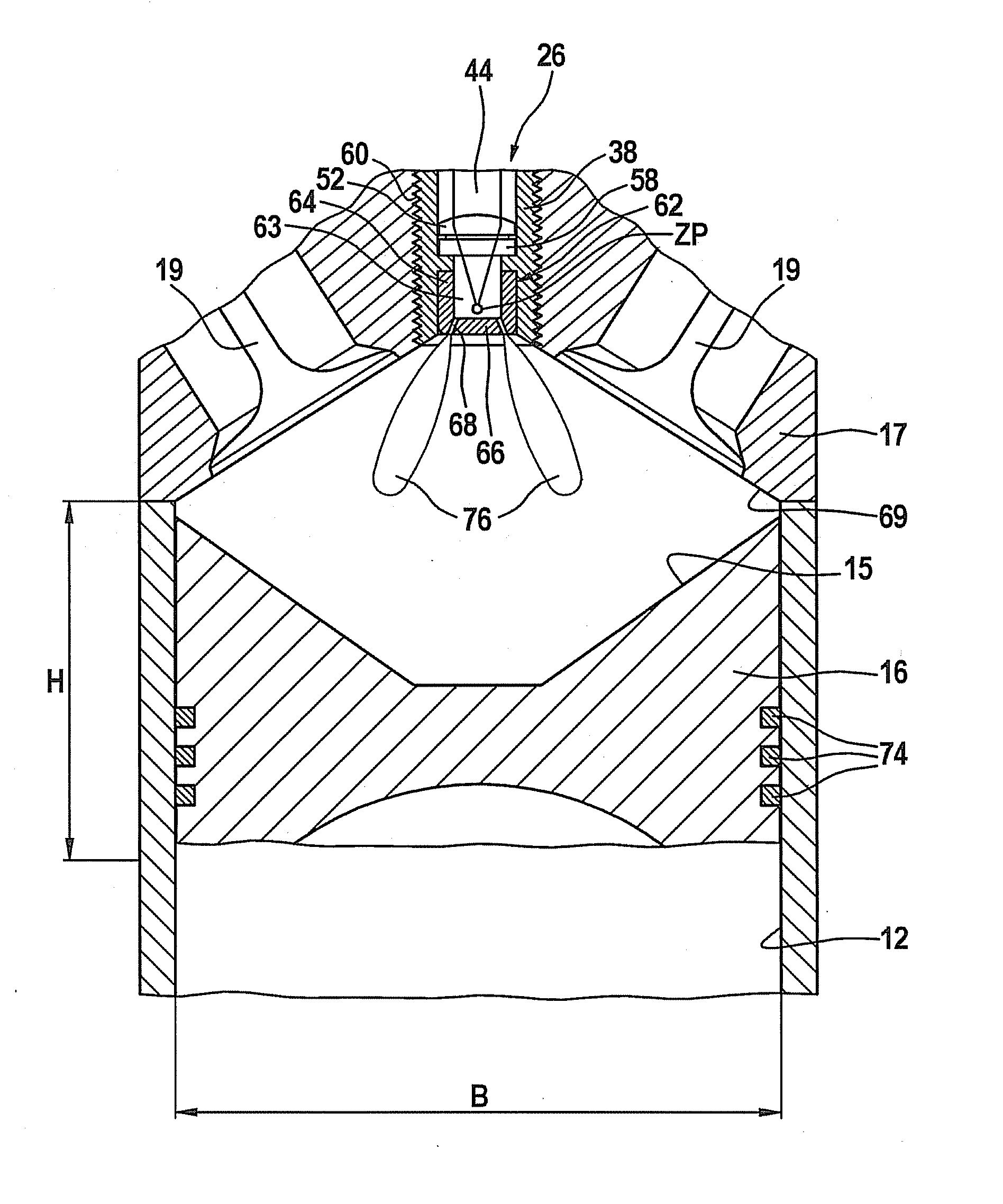
[0010]Since it is provided, according to the exemplary embodiments and / or exemplary methods of the present invention that the combustion chamber is to be designed to be spheroidal, in particular spherical, and in particular point-symmetrical with the ignition spot of the ignition laser at the point in time of ignition of the fuel-air mixture in the combustion chamber, the travel times of the flame front until reaching the combustion chamber wall are almost of the same short length everywhere. The result is a very compact combustion chamber shape and a favorable surface / volume ratio of the combustion chamber. The wall heat losses are therefore reduced and the efficiency of the internal combustion engine is further increased. The risk of so-called knocking combustion is also reduced and the internal combustion engine according to the present invention often manages without swirl flows or quench flows.
[0011]Due to the oscillating movement of the piston, it is self-evident that the shape of the combustion chamber naturally depends on the position of the crankshaft or the position of the piston in the cylinder. Therefore, in the internal combustion engine according to the present invention, emphasis is placed on the shape of the combustion chamber at the start of ignition. In other words, this ensures that even during the subsequent very short combustion time, the combustion chamber will have a favorable geometry for the combustion process.
[0015]Advantageous embodiments of the present invention provide that the combustion chamber roof and the piston bottom are planar, frustoconical and / or dome-shaped. The advantages according to the exemplary embodiments and / or exemplary methods of the present invention are easily implemented by using these geometries.
[0016]It has additionally proven advantageous if, at the ignition point, the maximum distance between the combustion chamber roof and the piston bottom corresponds approximately to the diameter of the piston. This ensures a very compact combustion chamber shape.
[0018]It is additionally provided that the antechamber has openings, which may be boreholes, which are directed into the combustion chamber. This achieves the result that the fuel-air mixture ignited in the antechamber passes through the opening in the form of an ignition flare into the combustion chamber according to the exemplary embodiments and / or exemplary methods of the present invention, where it ensures a rapid burn-up of the fuel mixture in the combustion chamber. Here again, the geometries according to the exemplary embodiments and / or exemplary methods of the present invention of the combustion chamber are advantageous.

Problems solved by technology

To nevertheless achieve rapid and thorough combustion of the mixture, a high velocity of flow and consequently a high turbulence must prevail in the combustion chamber.
To generate these flows and the resulting turbulence, substantial charge cycle losses occur and / or unfavorable chamber geometries in which the ratio between the surface area and the volume is great are required, so that high wall heat losses occur.
The charge cycle losses as well as the wall heat losses reduce the efficiency of the internal combustion engine.

Method used


Image

  • Gas engine having a laser ignition device
  • Gas engine having a laser ignition device
  • Gas engine having a laser ignition device

Examples


Embodiment Construction

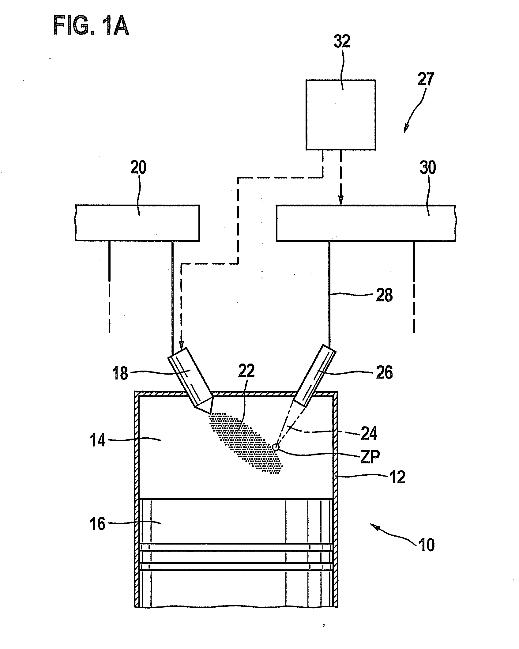
[0026]An internal combustion engine is labeled with reference numeral 10 on the whole in FIG. 1a. It may be used to drive a motor vehicle (not shown). Internal combustion engine 10 usually has several cylinders, only one of which is labeled with reference numeral 12 in FIG. 1a. A combustion chamber 14 of cylinder 12 is delimited by a piston 16. Fuel enters combustion chamber 14 directly through an injector 18, which is connected to a fuel pressure accumulator 20, also known as a rail. Alternatively, the fuel-air mixture may also be formed outside of combustion chamber 14, for example, in an intake manifold.

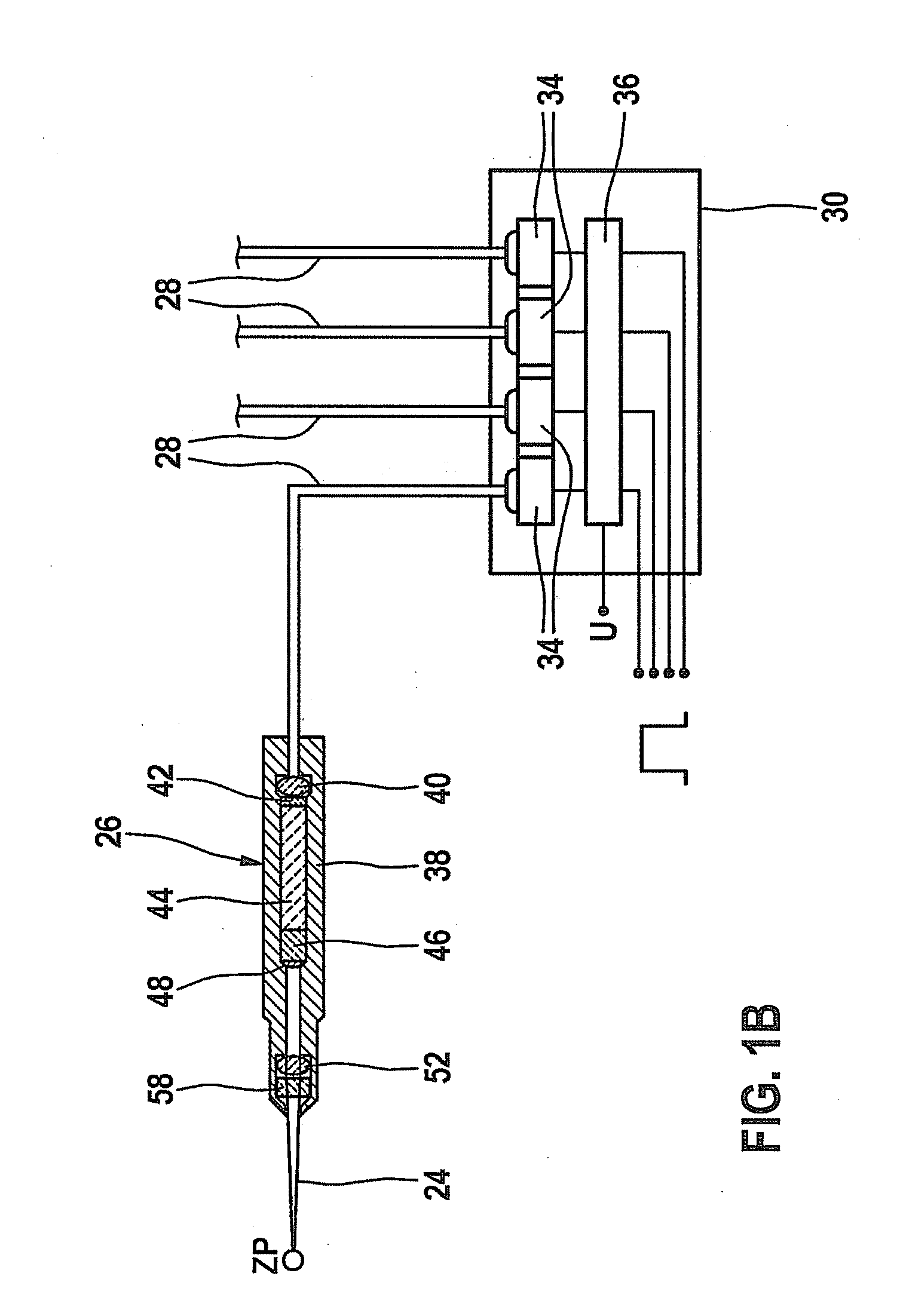
[0027]Fuel-air mixture 22 in combustion chamber 14 is ignited by a laser pulse 24 emitted into combustion chamber 14 by a laser ignition device 27, which includes an ignition laser 26. The ignition in combustion chamber 14 may also be prepared in an antechamber (not shown in FIG. 1) situated upstream from the combustion chamber. Ignition laser 26 is supplied via a fiber optic ligh...


PUM


Abstract

An internal combustion engine, in particular a gas engine, is described, which is equipped with a laser ignition device, and the combustion chamber has an essentially point-symmetrical shape at the ignition point.

Description

FIELD OF THE INVENTION[0001]The present invention relates to an internal combustion engine equipped with a laser ignition device, in particular a gas engine.BACKGROUND INFORMATION[0002]German patent document DE 10 2004 001 554 A1 discusses a laser ignition device for igniting an air-fuel mixture in an internal combustion engine, an ignition laser of the laser ignition device protruding into a combustion chamber of the internal combustion engine. The ignition laser is supplied optically by a pumped light source via an optical fiber.[0003]Large-scale gas engines are usually operated near the lean limit of a fuel-air mixture in order to achieve a good efficiency. A stable flame core must be formed during ignition, so that the fuel-air mixture in the combustion chamber may be burned afterward as rapidly as possible. Specifically in the case of gas engines operated in the extremely lean range, it is of utmost importance to reduce the combustion time and thereby increase engine efficiency...

Claims


Application Information

Patent Timeline
Patent Type & Authority Applications(United States)
IPC IPC(8): F02P23/04
CPCF02B19/12F02B23/101F02P23/04Y02T10/125F02M21/0275Y02T10/12
Inventor WEINROTTER, MARTINHERDEN, WERNERWOERNER, PASCALRAIMANN, JUERGEN
Owner ROBERT BOSCH GMBH
Learn More