Delay inversely proportional to temperature timer circuit

a timer circuit and delay technology, applied in the field of timer circuits, can solve the problems of timer delay, constant delay, inadequate conventional timers, etc., and achieve the effect of reducing the resistance of the pull-down path, and reducing the delay of timer

Inactive Publication Date: 2010-01-05
MONTEREY RES LLC
View PDF7 Cites 9 Cited by
  • Summary
  • Abstract
  • Description
  • Claims
  • Application Information

AI Technical Summary

Benefits of technology

[0009]In one embodiment, the novel timer circuit includes a pull-down path that includes a plurality of parallel coupled transistors which are coupled to the reference signal. Resistance of the pull-down path is reduced as the reference signal is increased and the reduced

Problems solved by technology

Most of these applications have a timing delay that changes proportional to changes in temperature.
During operation, this approach produces a constant delay based on the capacitor loads and requires designing for a worst-case delay with no real-time adjustment for temperatu

Method used


Image

  • Delay inversely proportional to temperature timer circuit
  • Delay inversely proportional to temperature timer circuit
  • Delay inversely proportional to temperature timer circuit

Examples


Embodiment Construction

[0018]In the following detailed description of the embodiments, numerous specific details are set forth in order to provide a thorough understanding of the present invention. However, it should be recognized by one skilled in the art that the present invention may be practiced without some specific details or with equivalents thereof. In other instances, well-known methods, procedures, components, and circuits have not been described in detail as not to unnecessarily obscure aspects of the embodiments.

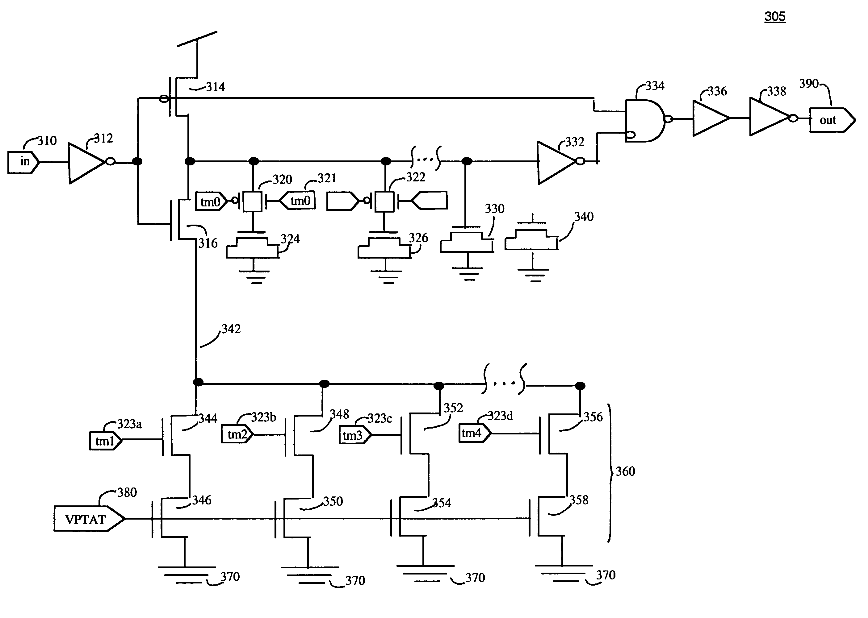
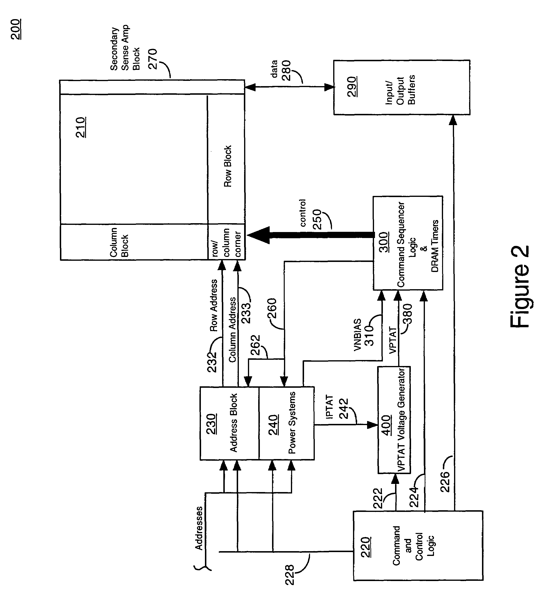
[0019]Accordingly, embodiments of the present invention provide a device and method for varying inversely the delay in the operation of a timer circuit responsive to changes in temperature. Although the novel timer circuit can be used in any circuit architecture, in one exemplary embodiment the timer circuit may be used in a memory device. Therefore, FIG. 2 illustrates one exemplary application of the novel timer circuit in accordance with one embodiment of the present invention. FIG. ...


PUM


Abstract

A timer circuit is disclosed. The timer, having a delay configured to track inversely with temperature of the memory device, includes a reference signal configured to increase in voltage, as the temperature of the memory device increases. The reference signal may be generated from a current that is derived from a bandgap reference circuit. The timer circuit includes a pull-down path made up of a plurality of selectable pull down transistors which are coupled to the reference signal at the gate. Resistance of the pull-down path is reduced as the reference signal is increased and the reduced resistance of the pull-down path decreases the delay of timer. A plurality of selectable delay elements may be preconfigured to adjust the delay and are coupled to the output path of the current starved inverter.

Description

RELATED U.S. APPLICATION[0001]This Application claims priority to the copending provisional patent application Ser. No. 60 / 456,491, entitled “INVERSELY PROPORTIONAL TO TEMPERATURE TIMER CIRCUIT,” with filing date Mar. 20, 2003, assigned to the assignee of the present application, and hereby incorporated by reference in its entirety.BACKGROUND OF THE INVENTION[0002]1. Field of the Invention[0003]The present invention relates to the field of timer circuits. More particularly, the present invention relates to a method and architecture for a timer circuit having a delay that is inversely proportional to temperature.[0004]2. Related Art[0005]There are a number of timer circuits known in the art that are applied in circuits that require an intentional delay for timing coordination. Most of these applications have a timing delay that changes proportional to changes in temperature. One common application of such a timer is in a basic ring oscillator circuit. Many applications, however, requ...

Claims


Application Information

Patent Timeline
IPC IPC(8): H03H11/26
CPCH03H11/265H03H11/54
Inventor SMITH, CHRISCHAPMAN, DAVEFISCUS, TIM
Owner MONTEREY RES LLC
Why Eureka
Try Eureka