Testing of transmitters for communication links by software simulation of reference channel and/or reference receiver

a technology of reference receiver and software simulation, which is applied in the direction of transmission monitoring, transmission monitoring/testing/fault-measurement system, electrical equipment, etc., can solve the problems of limited arithmetic precision of hardware reference receiver and finite length equalizer of edc receiver that can be reasonably implemented in hardware, and achieves more accurate measurement, eliminate inaccuracies inherent in separate or manual measurements, and accurate measurement of oma

Active Publication Date: 2010-01-05
MARVELL ASIA PTE LTD
View PDF38 Cites 14 Cited by
  • Summary
  • Abstract
  • Description
  • Claims
  • Application Information

AI Technical Summary

Benefits of technology

[0020]In one approach, a data test pattern is applied to the transmitter under test and the transmitter output is sampled using standard test equipment. The captured waveform is processed through a software simulation of the reference optical fiber (i.e., reference channel) and the reference receiver (which includes an equalizer). The use of a standard software simulation of the reference channel and the reference receiver avoids the difficulties inherent with a hardware receiver and allows a more accurate measurement of unequalizable signal impairments. The need for a hardware reference transmitter, fiber, or reference receiver is eliminated, thus saving significant costs. In this way, TWDP can be measured for optical fiber communication systems using EDC.
[0023]The software simulator can also perform measurement of optical modulation amplitude (OMA) and waveform baseline. The computation of these quantities based on the captured waveform (including earlier or later processed versions of the captured waveform) eliminates the inaccuracies inherent in separate or manual measurements. For example, these quantities can be computed from the raw digitized waveform captured by the waveform capture device, from the waveform after some pre-processing (e.g., after re-sampling, truncation and / or data alignment) or from waveforms after simulation of propagation. Techniques are disclosed that yield more accurate measurements for highly distorted signals. This is advantageous because TWDP depends strongly on OMA, and the accurate measurement of OMA may be very difficult for distorted transmit waveforms that, in spite of this distortion, are acceptable when EDC is used in the receiver. In another variation, the software automatically corrects for the optimal DC offset (bias) value. Since the TWDP value is sensitive to offset of the waveform, automatic offset optimization improves reproducibility of the measured TWDP. This can be accomplished by adding an extra tap to the feedforward filter of the equalizer.

Problems solved by technology

This approach has advantages since using a hardware reference receiver has significant problems.
However, an EDC receiver that can be reasonably implemented in hardware will have a finite length equalizer with limited arithmetic precision.
Therefore, the results from a hardware reference receiver will not fully reflect the theoretical TWDP results and may be strongly influenced by the actual reference receiver implementation.

Method used


Image

  • Testing of transmitters for communication links by software simulation of reference channel and/or reference receiver
  • Testing of transmitters for communication links by software simulation of reference channel and/or reference receiver
  • Testing of transmitters for communication links by software simulation of reference channel and/or reference receiver

Examples


Embodiment Construction

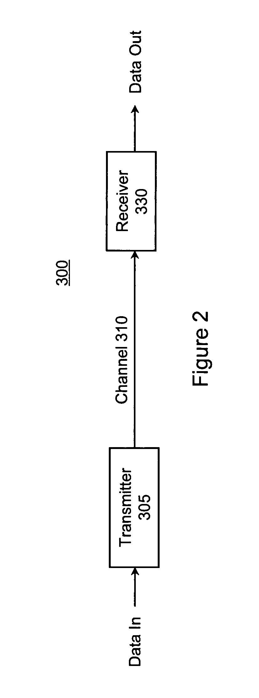
[0033]FIG. 2 is a block diagram of a communications link 300 suitable for use with the current invention. The link 300 includes a transmitter 305 coupled through a channel 310 to a receiver 320. The overall system 300 may suffer from various impairments in transmitting data from the transmitter 305 to the receiver 320. The transmitters 305, channels 310 and receivers 320 may be various types, depending on the end application. Microwave, RF, cable, and optical fiber are some examples of different media for the channel 310. Different types of modulation may be used by the transmitter 305. Some examples are on-off keying, QAM, PSK, and OFDM. Similarly, the receiver 315 can also take the various forms corresponding to these different modulation formats.

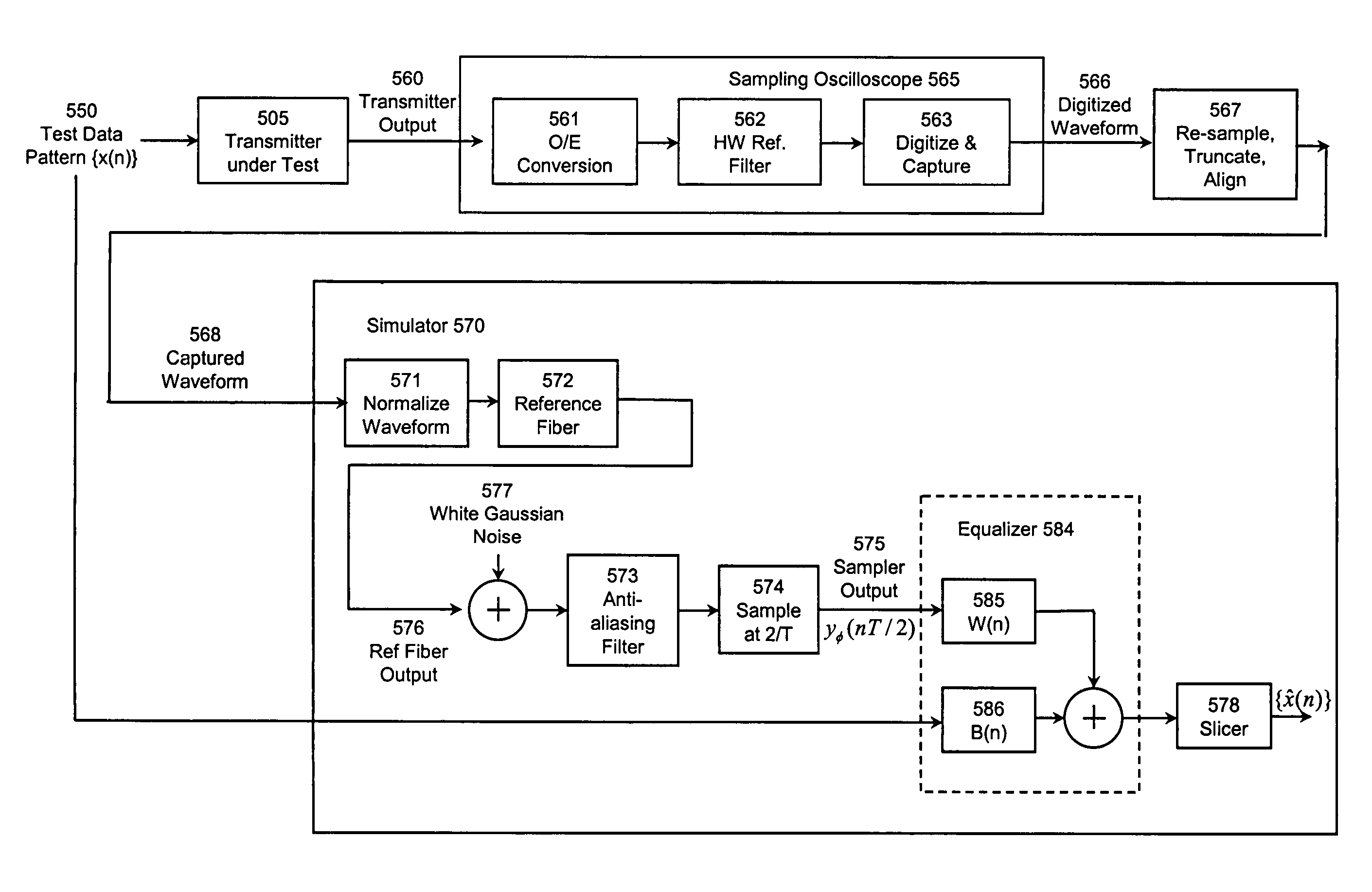
[0034]FIGS. 3 and 4 are block diagrams of a test system according to the current invention. The purpose of the test system is to test the transmitter, for example for compliance with a specific standard. In FIG. 3, a data test pattern 450...


PUM


Abstract

A transmitter for a communications link is tested by using a (software) simulation of a reference channel and / or a reference receiver to test the transmitter. In one embodiment for optical fiber communications links, a data test pattern is applied to the transmitter under test and the resulting optical output is captured, for example by a sampling oscilloscope. The captured waveform is subsequently processed by the software simulation, in order to simulate propagation of the optical signal through the reference channel and / or reference receiver. A performance metric for the transmitter is calculated based on the processed waveform.

Description

CROSS-REFERENCE TO RELATED APPLICATION(S)[0001]This application claims priority under 35 U.S.C. §119(e) to each of the following U.S. Provisional Patent Applications: Ser. No. 60 / 638,788, “Proposed TP-2 Test Methodology,” filed Dec. 22, 2004; Ser. No. 60 / 641,834, “Proposed TP-2 Test Methodology,” filed Jan. 5, 2005; Ser. No. 60 / 643,234, “Proposed TP-2 Test Methodology with MATLAB Script,” filed Jan. 11, 2005; Ser. No. 60 / 677,911, “New Approach To Measure Tx Signal Strength And Penalty,” filed May 4, 2005; Ser. No. 60 / 690,190, “Improvements To Transmit Waveform And Dispersion Penalty Algorithm,” filed Jun. 13, 2005; Ser. No. 60 / 698,435, “Method To Accurately Measure Bias And Optical Modulation Amplitude For a Distorted Optical Waveform,” filed Jul. 11, 2005; Ser. No. 60 / 701,637, “Method To Extract Square-Wave-Based Bias And Optical Modulation Amplitude For A Distorted Optical Waveform,” filed Jul. 21, 2005; Ser. No. 60 / 707,282, “Method To Extract Square-Wave-Based Bias And Optical Mo...

Claims


Application Information

Patent Timeline
Patent Type & Authority Patents(United States)
IPC IPC(8): H04B10/00
CPCH04B10/07H04B10/0731
Inventor SWENSON, NORMAN LVOOIS, PAULLINDSAY, THOMAS A.ZENG, STEVE C.
Owner MARVELL ASIA PTE LTD
Why Eureka
Try Eureka