
Method and apparatus for developing a metadata-infused software program for controlling a robot

a robot and metadata technology, applied in the direction of programme control, total factory control, instruments, etc., can solve the problems of reducing the competitive advantage of robots, requiring detailed knowledge, and limited in their ability to implement new features

Active Publication Date: 2010-01-05
ABB RES LTD
View PDF30 Cites 53 Cited by
  • Summary
  • Abstract
  • Description
  • Claims
  • Application Information

AI Technical Summary

Problems solved by technology

One major issue with current control programming is that it requires detailed knowledge of both the particular control language in use and the process in which the controlled device is used.
Robot manufacturers have resisted making a common language for industrial robots in the belief that they would be limited in their ability to implement new features and would lose their competitive advantage.
Also, solutions that localize the robot language to the user's native language do not address the fundamental problem that the user must still learn the robot language, even if some of the words are in his native tongue.
Another major issue with current robot programming is that teaching the robot the process path can be a tedious and complex task.
Also, the process may require large numbers of path points for complex curves, a process path accuracy that is difficult for an operator to achieve by hand, and other special process specific issues such as strict tool orientation requirements that an operator may have difficulty programming.
In many cases, Computer Aided Design (CAD) models for the workpiece are not available, which prevents off-line teaching of complicated paths in one of the various robotics simulation packages available on the marketplace.
Thus the user is left with hours or even weeks of path teaching time when programming very complicated parts or processes.
Additionally, robot programs themselves have been criticized for being obtuse and written according to the whims and knowledge level of the particular programmer.
The structure of the program itself may not be consistent even between two robots performing the same process.
Too often, the new programmer finds it quicker to rewrite the entire program rather than try to understand and improve on the existing one.
Such programming methods have met with limited success in complex robotic applications because of the difficulty in developing a complex program using standard icons.
Common parts of even a simple robot routine, such as an error handler, can be difficult to graphically program in a simple and direct manner.
Moreover, the standard icons may not be very descriptive and may require a programmer to be intimately familiar with the symbology of the graphical programming language.
As a result, flowchart-type graphical programs can be even more difficult to understand than conventional code programs.
In addition, flowchart-type graphical programming is primarily focused on graphically representing a robot program, rather than facilitating proper and / or more efficient robot programming.
For example, with current programming technology, it is not possible to know if position data in a move command has been taught, should be taught, or if it has been tested.
Also, currently it is not possible to know how different lines or sections of a program are related to each other.
Another unresolved area in current robot programming methodologies is the separation of the process to be performed from the particular data of an installation.
Previous attempts to standardize robot programs have met with limited success since they either sacrificed flexibility for commonality by enforcing a strict structure, or they merely left open spaces in the standard program for users to insert code to fit their unique needs.
The programmer is not assisted by the robot in any way because the robot itself has no knowledge about how to accomplish the process.

Method used


Image

  • Method and apparatus for developing a metadata-infused software program for controlling a robot
  • Method and apparatus for developing a metadata-infused software program for controlling a robot
  • Method and apparatus for developing a metadata-infused software program for controlling a robot

Examples


Embodiment Construction

[0033]It should be noted that in the detailed description that follows, identical components have the same reference numerals, regardless of whether they are shown in different embodiments of the present invention. It should also be noted that in order to clearly and concisely disclose the present invention, the drawings may not necessarily be to scale and certain features of the invention may be shown in somewhat schematic form.

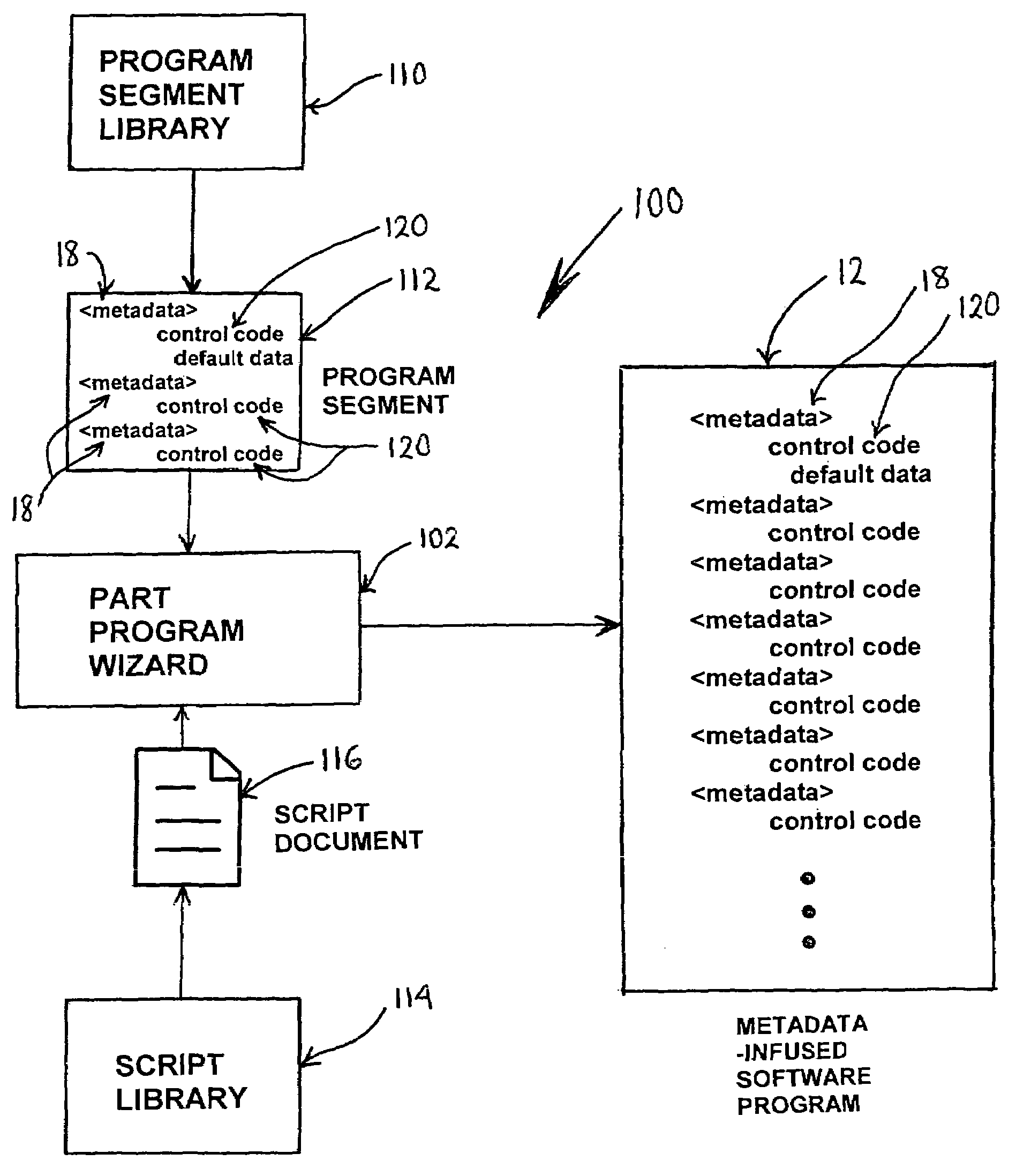
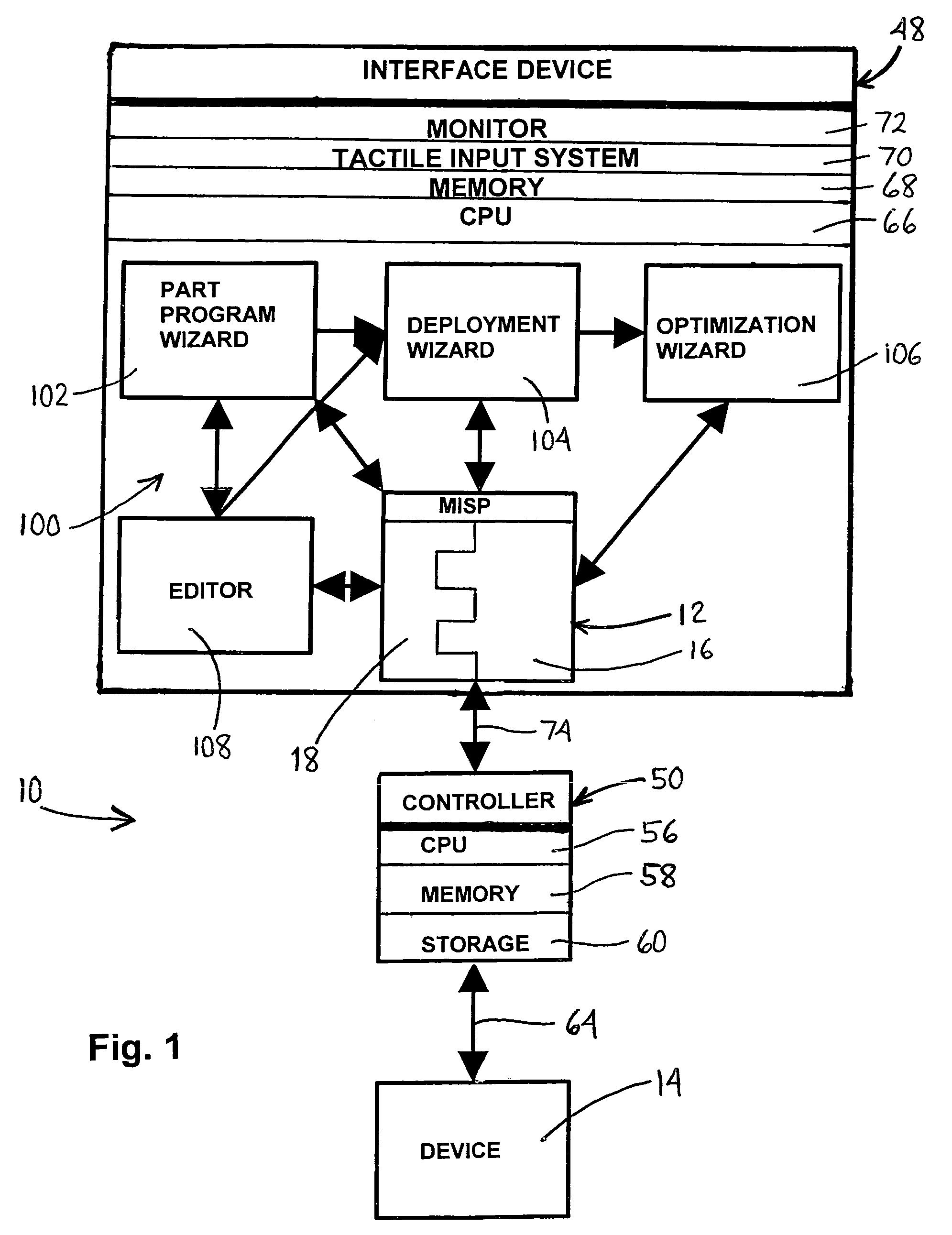
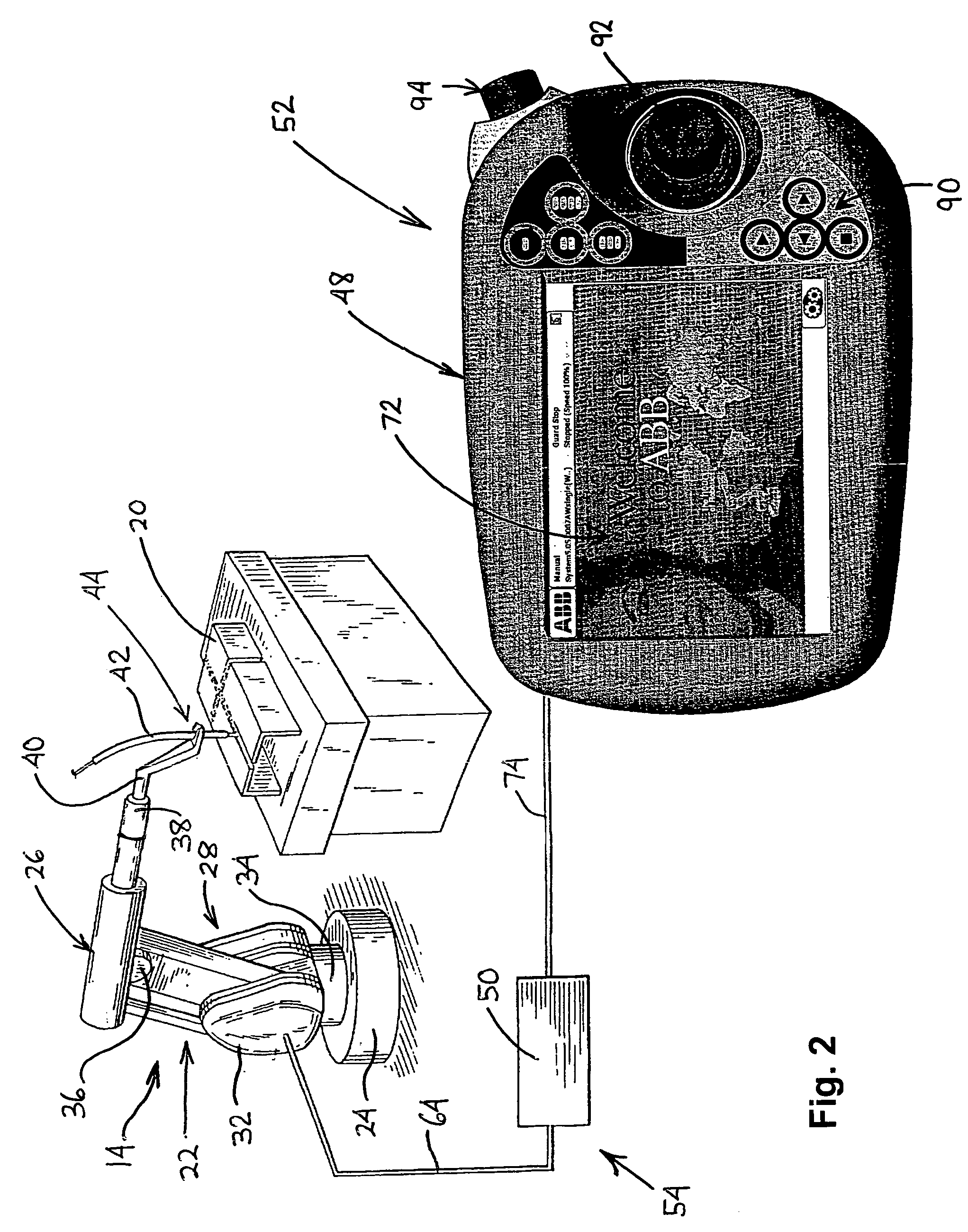
[0034]Referring now to FIG. 1, the present invention is directed to a method and apparatus 10 for developing and executing metadata-infused software programs 12 for controlling a device 14 to perform a desired function or operation. A metadata-infused software program 12 includes a control program 16 comprising control code written in an interpreted language, such a language based on the C programming language. The control program 16 is operable to control the device 14 and is interleaved with metadata 18 to maintain state information of the control program ...


PUM


Abstract

The present invention is directed to a method and apparatus for developing a metadata-infused software program for controlling a device, such as a robot. A first library of software segments with metadata and a second library of script documents are provided. A part program wizard uses a script document selected from the second library to display queries on a screen of an interface device. Using input information received in response to the queries, the part program wizard selects and combines software segments from the first library to produce the metadata-infused software program. The metadata identifies the selected software segments and includes statuses of the selected software segments. A graphical representation of the metadata infused software program is displayed on the screen and conveys the statuses of the software segments. A deployment wizard is utilized to teach data points for the metadata-infused software program.

Description

BACKGROUND OF THE INVENTION[0001]This invention relates to software application development and more particularly to the development of a software application for controlling a device, such as a robot.[0002]A software application for controlling a device is often written in a language that has been specially developed by a manufacturer of the device. Although the languages of different manufacturers may be based on the same high level language, such as the C programming language, each manufacturer's language typically has its own syntax and semantics. This is especially true in the field of robotics. For example, one robot manufacturer may write a command to linearly move a robot from one point or position to another as “MoveL toPoint1, speed100, zone1, tool1;” and a different manufacturer as “PTP P1 CONT Vel=100% PDATA1”. Each language is meant to be readable by an experienced programmer who may, using that language, reasonably write and test a program to do the job at hand. There ...

Claims


Application Information

Patent Timeline
Patent Type & Authority Patents(United States)
IPC IPC(8): G05B15/00
CPCB25J9/1656G05B19/0426G06F8/20G05B2219/23126G05B2219/23254G05B2219/23261G05B2219/23291Y02P90/083G05B2219/23389G05B2219/35489G05B2219/36032G05B2219/40387G05B2219/23293Y02P90/02
Inventor FUHLBRIGGE, THOMAS A.ROSSANO, GREGORYZHANG, HUIWANG, JIANJUNGAN, ZHONGXUE
Owner ABB RES LTD
Learn More