Monohull sailing vessel having a lifting hydrofoil

a technology of lifting hydrofoil and sailing vessel, which is applied in the direction of marine propulsion, special-purpose vessels, vessel construction, etc., can solve the problems of vessel failure, complex devices, and vessel sunk in the bottom of the vessel

Active Publication Date: 2010-01-12
DYNAMIC STABILITY SYST
View PDF13 Cites 15 Cited by
  • Summary
  • Abstract
  • Description
  • Claims
  • Application Information

AI Technical Summary

Benefits of technology

[0010]The illustrated embodiments of the present invention describe a hydrofoil system for monohull sailing vessels which provide increased performance from forces derived from dynamic effects for high performance monohull sailing vessels, in a manner that is inherently fail-safe and that in no way affects the ultimate seaworthiness of the vessel. The illustrated embodiments of the invention can also be configured for use in other lower performance sailing vessels such as cruising yachts in order to reduce the required sailing heel angles, increase the dampening of roll, and thus significantly improve the comfort level of the crew and performance of the vessel.
[0011]In one embodiment formed in accordance with the present invention, a lifting hydrofoil surface(s) is provided having a medium to high aspect ratio, one suitable example being a hydrofoil having an aspect ratio of about 2:1 or greater, which extends directly outward from a leeward side of a sailing vessel in an approximately horizontal orientation (when the vessel is at an optimum upwind heel angle) to provide a righting moment to counteract a heeling moment caused by the sails and a lifting force to partially lift the vessel out of the water to reduce drag.

Problems solved by technology

It also has the major drawback that any failure of the mechanical controlling devices or keel itself can and has resulted in totally uncontrolled movement of the ballasted keel and the subsequent destruction of the keel support area of the hull with disastrous and terminal damage that can and has resulted in the foundering of the vessel.
However, such devices are complicated, prone to failure, require constant adjustment, require a highly knowledgeable operator, are costly, and add weight.
However, like controlling the AoA, controlling the projected area of the hydrofoil results in a system that is complicated, prone to failure, requires constant adjustment, requires a highly knowledgeable operator, is expensive, and adds weight.
These low aspect ratio foils have been found to be inefficient in terms of lift to drag ratios and have been found to have insufficient span to provide a significant increase to the total righting moment.
Thus the total beneficial effects have not been sufficient to overcome the inherent additional drag and their development has been abandoned.
In addition, the fore and aft location of these foils has been such that they would significantly increase the total drag of the vessel and thus not result in any performance increases and again this has discouraged further progress along this line.

Method used


Image

  • Monohull sailing vessel having a lifting hydrofoil
  • Monohull sailing vessel having a lifting hydrofoil
  • Monohull sailing vessel having a lifting hydrofoil

Examples


Embodiment Construction

[0045]The following description will describe the invention in relation to preferred embodiments of the invention, namely a hydrofoil system for a monohull sailing vessel. The invention is in no way limited to these preferred embodiments as they are used purely to exemplify the invention only and it is noted that possible variations and modifications are readily apparent without departing from the scope of the invention.

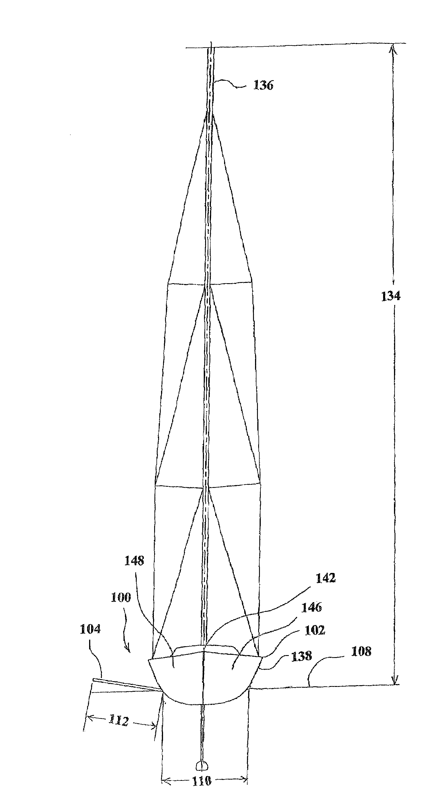
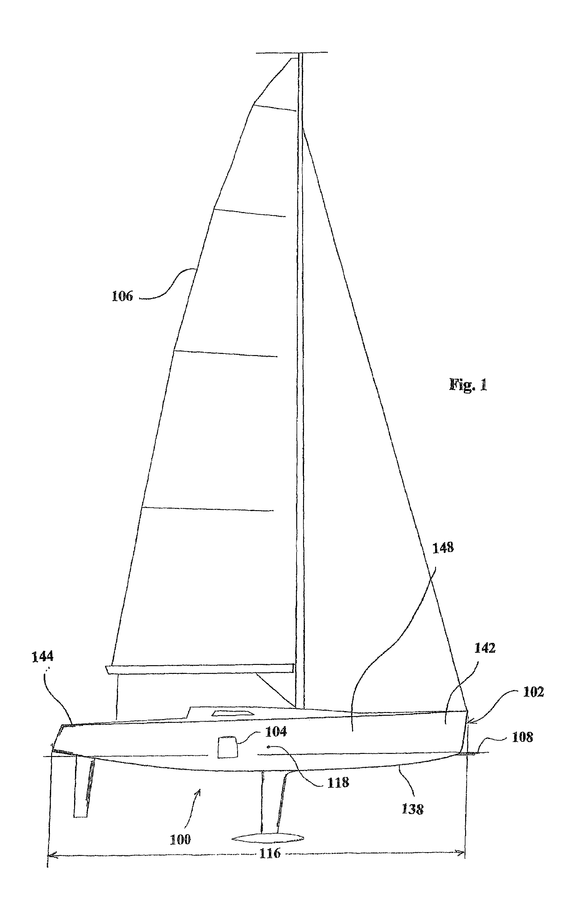
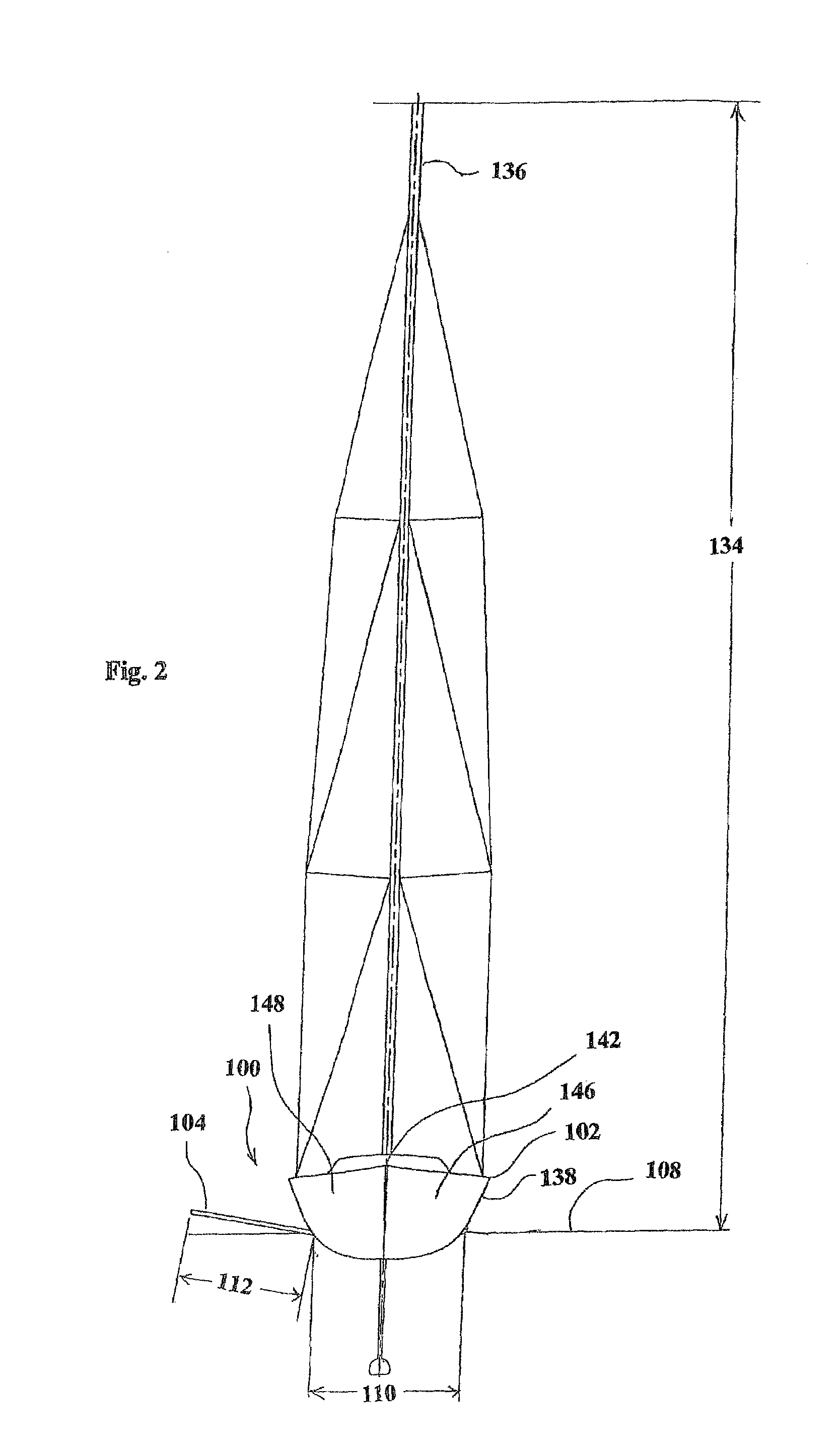
[0046]Referring to FIGS. 1-6, one embodiment of a hydrofoil system 100 formed in accordance with the present invention is shown as applied to a monohull sailing vessel 102. The monohull sailing vessel 102 has a hull 138 with a longitudinal dimension 140, a bow 142, a stern 144, a port side 146, and a starboard side 148. The hydrofoil system 100 includes a lifting hydrofoil 104. The lifting hydrofoil 104 is positionable between a port extended position (not shown) in which the lifting hydrofoil 104 extends outward of the port side 146 of the hull 138 and into the pass...


PUM


Abstract

A monohull sailing vessel (102, 202, 402, and / or 502) having a lifting hydrofoil (104 and / or 204) having a stowed position and a deployed position in which the hydrofoil extends outward of a leeward side of the hull (138). The hydrofoil may have an aspect ratio greater than 2.5:1, may be oriented at an angle of attack between 2 and 6 degrees, and may be oriented at a mean angle (124) of between 5 and 20 degrees to horizontal. The hydrofoil may have a projected area adapted provide a righting moment and a lifting force for partially but not fully lifting the vessel out of the water. The hydrofoil may have an exposed span (112) that is greater than about 7% of a height of the tallest mast (134). The vessel may include an actuation assembly (128, 228, 308, and / or 316) for moving the hydrofoil between the stowed and deployed positions.

Description

TECHNICAL FIELD OF THE INVENTION[0001]The invention relates to monohull sailing vessels, and is more specifically directed to monohull sailing vessels having a lifting hydrofoil for improving the performance of the monohull sailing vessel.BACKGROUND OF THE INVENTION[0002]In previously developed monohull sailing vessels, heeling forces from the sail plan are counteracted by the use of a fixed keel, the movement of the crew, movement of water or other ballast, or lately the utilization of swinging keels in the which the ballasted keel is mechanically swung towards the windward side of the vessel, or any combination of the above features.[0003]The use of the swinging ballasted keel has provided the most benefit in terms of extracting more speed from sailing vessels of all sizes, but has resulted in a system that requires significant power input from either crew or stored power systems to operate. It also has the major drawback that any failure of the mechanical controlling devices or k...

Claims


Application Information

Patent Timeline
Patent Type & Authority Patents(United States)
IPC IPC(8): B63B35/00
CPCB63B39/06B63H9/04B63B41/00B63B43/04B63B2035/009B63B1/30B63B2039/065B63B2001/281
Inventor WELBOURN, HUGH BURKEWOOD
Owner DYNAMIC STABILITY SYST
Why Eureka
Try Eureka