Non-equilibrium plasma discharge type ignition device

a plasma discharge and ignition device technology, applied in the direction of ignition automatic control, spark plugs, anti-theft devices, etc., can solve the problem of inevitable increase in power consumption due to discharge, and achieve the effect of expanding the lean burn limit of the internal combustion engine, achieving the desired ignition performance, and low energy consumption

Inactive Publication Date: 2010-01-12
NISSAN MOTOR CO LTD
View PDF17 Cites 22 Cited by
  • Summary
  • Abstract
  • Description
  • Claims
  • Application Information

AI Technical Summary

Benefits of technology

[0005]It is therefore an object of this invention to realize a desired ignition performance with low energy consumption, and to expand a lean burn limit of an internal combustion engine.

Problems solved by technology

According to the prior art ignition device, although the ignition performance is improved, an increase in power consumption due to the discharge is inevitable.

Method used


Image

  • Non-equilibrium plasma discharge type ignition device
  • Non-equilibrium plasma discharge type ignition device
  • Non-equilibrium plasma discharge type ignition device

Examples


second embodiment

[0076]Referring to FIG. 8, this invention will be described.

[0077]The ignition device according to this embodiment differs from that of the first embodiment in that a plurality of projections 52a are provided on the cylindrical electrode 52 of the spark plug 50. The other components of this ignition device are identical to those of the ignition device according to the first embodiment of this invention.

[0078]The spark plug 50 is provided with a plurality of projections 52a arranged in the axial and radial directions on the inner peripheral surface of the cylindrical electrode 52 to protrude into the ignition chamber 55. The projections 52a are formed of a conductive material, and the distal ends of all the projections 52a are at a same distance from the insulating member 53.

[0079]In the spark plug 50, the non-equilibrium plasma discharge is effected between the projections 52a of the cylindrical electrode 52 and the insulating member 53. The number of streamers 56 formed in the igni...

third embodiment

[0083]Referring to FIG. 9, this invention will be described.
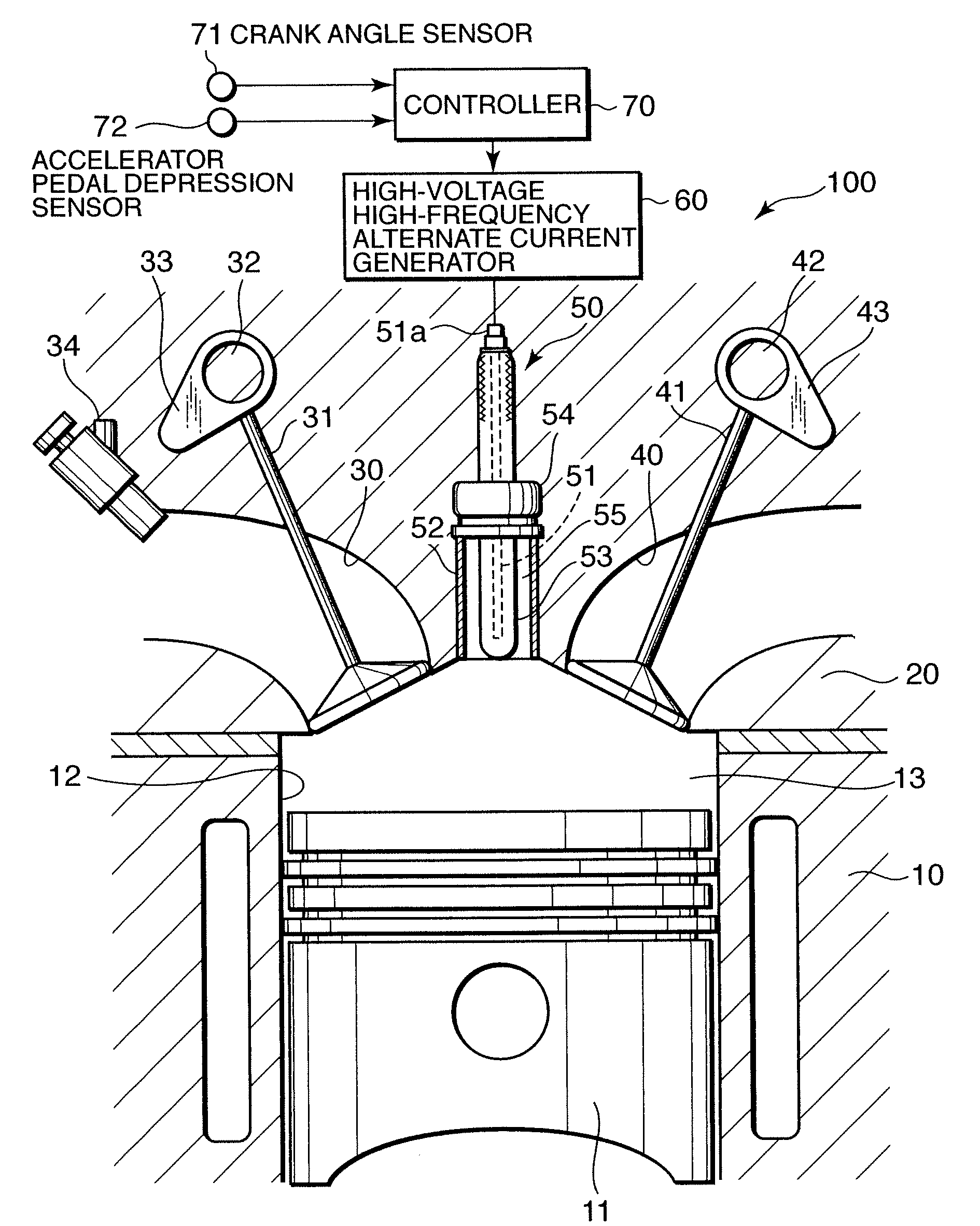
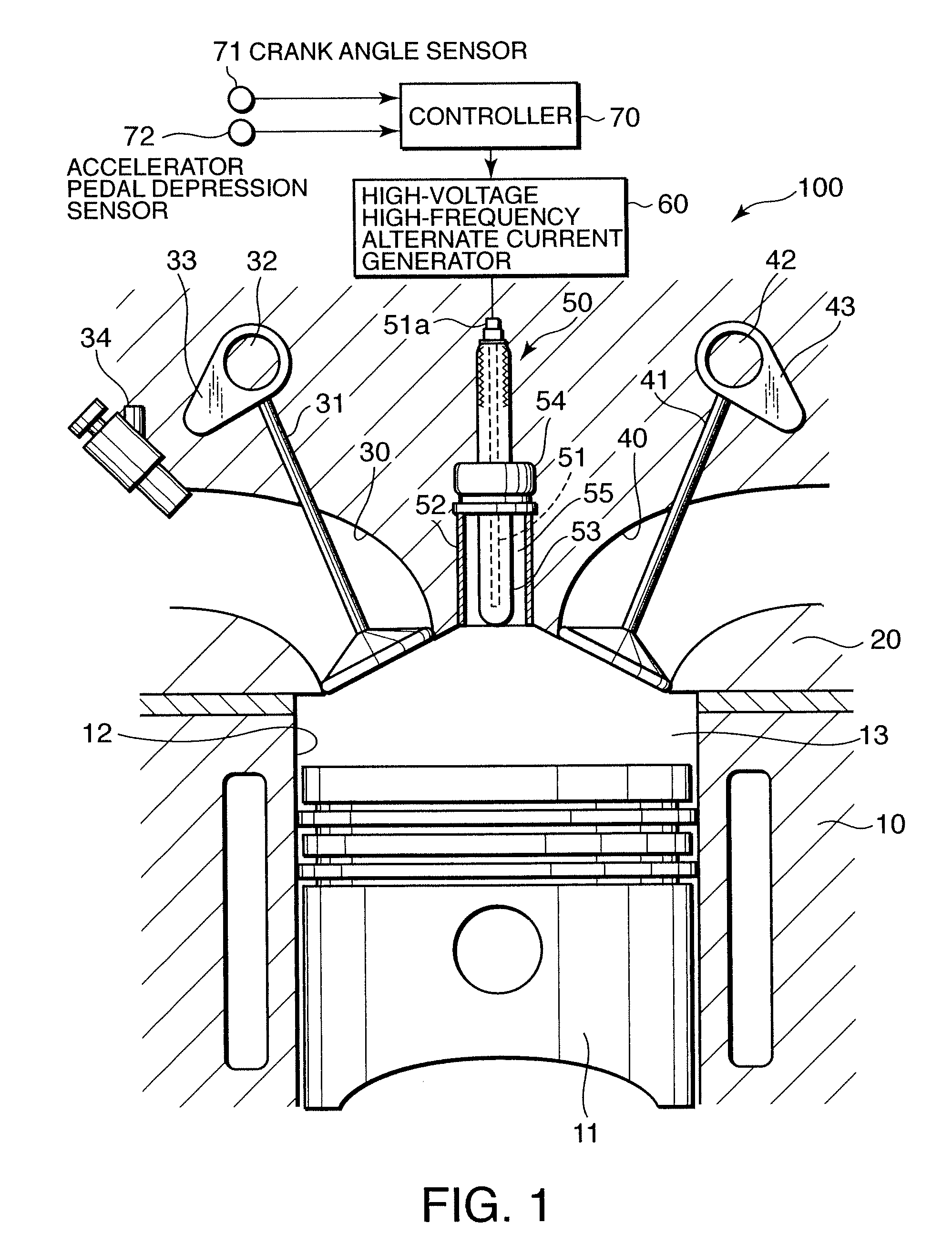
first embodiment

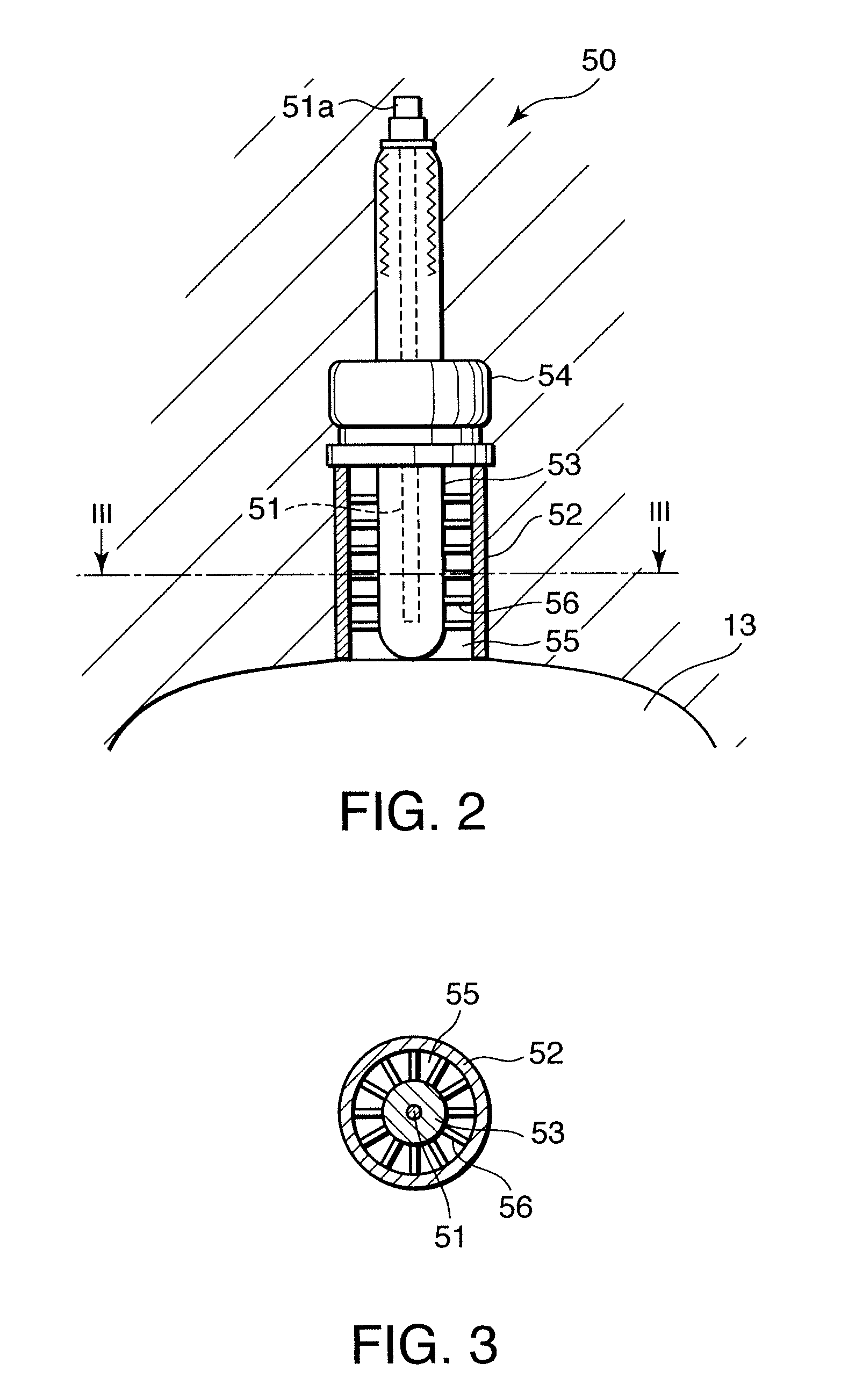
[0084]In the ignition device according to this embodiment, the insulating member 53 of the spark plug 50 is in contact with the inner periphery of the cylindrical electrode 52, and covers the cylindrical electrode 52. In other words, the insulating member 53 covers not the first electrode but the second electrode. The other components of this ignition device are identical to those of the ignition device according to the

[0085]The insulating member 53 is formed into a cylindrical shape having a bottom. The insulating member 53 is fitted into the inner peripheral surface of the cylindrical electrode 52. The lower end of the insulating member 53 extends lower than the lower end of the cylindrical electrode 52 and protrudes into the combustion chamber 13. The space between the bar-like center electrode 51 and the insulating member 53 functions as the ignition chamber 55. The ignition chamber 55 communicates with the combustion chamber 13 via an opening directed to the combustion chamber ...


PUM


Abstract

An ignition device performs spark ignition to a fuel mixture in a combustion chamber (13) of an internal combustion engine (100, 101) by using a spark plug (50). The spark plug (50) includes a first electrode (51), a second electrode (52, 11a, 11b, 21), and an insulating member (53, 11c) which is formed from dielectric substance and interposed between the first electrode (51) and the second electrode (52, 11a, 21). By impressing an alternating current between the first electrode (51) and the second electrode (52, 11a, 21), non-equilibrium plasma discharge between the insulating member (53, 11c) and one of the first electrode (51) and the second electrode (52, 11a, 21) is promoted. Igniting the fuel mixture by the non-equilibrium plasma discharge achieves a high ignition performance is achieved with low energy consumption.

Description

FIELD OF THE INVENTION[0001]This invention relates to an ignition device which ignites a fuel mixture to be combusted by an internal combustion engine by non-equilibrium plasma discharge.BACKGROUND OF THE INVENTION[0002]JPH 10-141191A published by the Japan Patent Office in 1996 proposes an ignition device which ignites a fuel mixture in a combustion chamber of an internal combustion engine through application of non-equilibrium plasma discharge. The non-equilibrium plasma discharge is also called low-temperature plasma discharge or corona discharge.[0003]The ignition device according to the prior art comprises two electrodes which effect a high-voltage discharge in the combustion chamber, and a pulse power source portion for impressing a short-pulse-width high-voltage alternating current between the electrodes to cause the non-equilibrium plasma discharge between the electrodes, and then generates equilibrium plasma discharge due to thermalization plasma, thereby igniting the fuel ...

Claims


Application Information

Patent Timeline
Patent Type & Authority Patents(United States)
IPC IPC(8): F02P5/145F02P3/01
CPCF01L13/0026F02P23/04H01T13/54H05H1/2406H05H1/52H01T13/50F01L2013/0073F02P5/00F02P9/007F02P3/01H05H2001/2418H05H1/2418
Inventor SHIRAISHI, TAISUKEURUSHIHARA, TOMONORITAKAHASHI, EIJI
Owner NISSAN MOTOR CO LTD
Why Eureka
Try Eureka