
Non-equilibrium plasma discharge type ignition device
a plasma discharge and ignition device technology, applied in the direction of electric ignition installation, mechanical equipment, machines/engines, etc., can solve the problems of inability to generate chain heat in the periphery, and inability to reduce the lean burn limit of internal combustion engines. , to achieve the effect of expanding the lean burn limit of internal combustion engines and improving ignition performan
- Summary
- Abstract
- Description
- Claims
- Application Information
AI Technical Summary
Benefits of technology
Problems solved by technology
Method used
Image

Examples
first embodiment
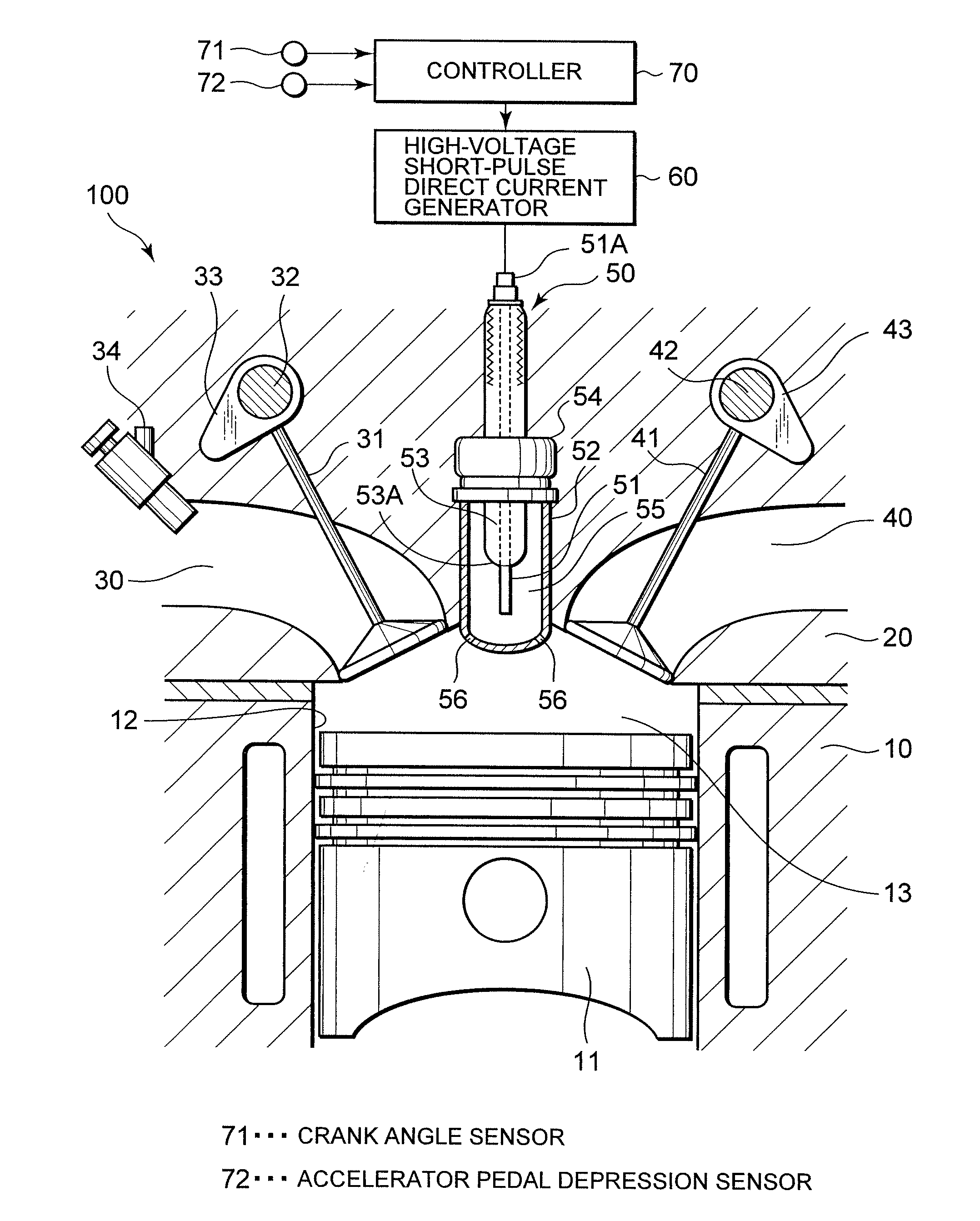
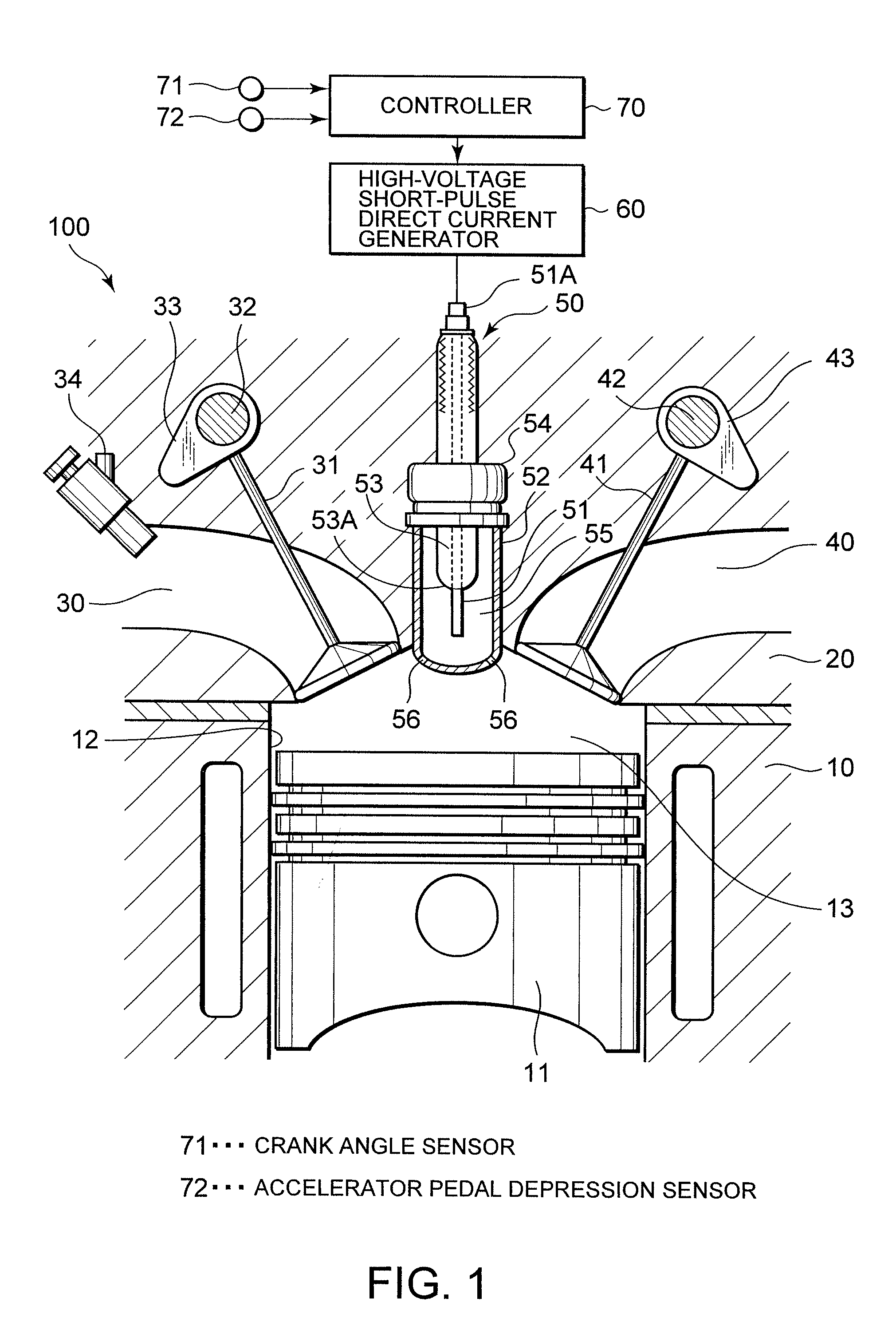
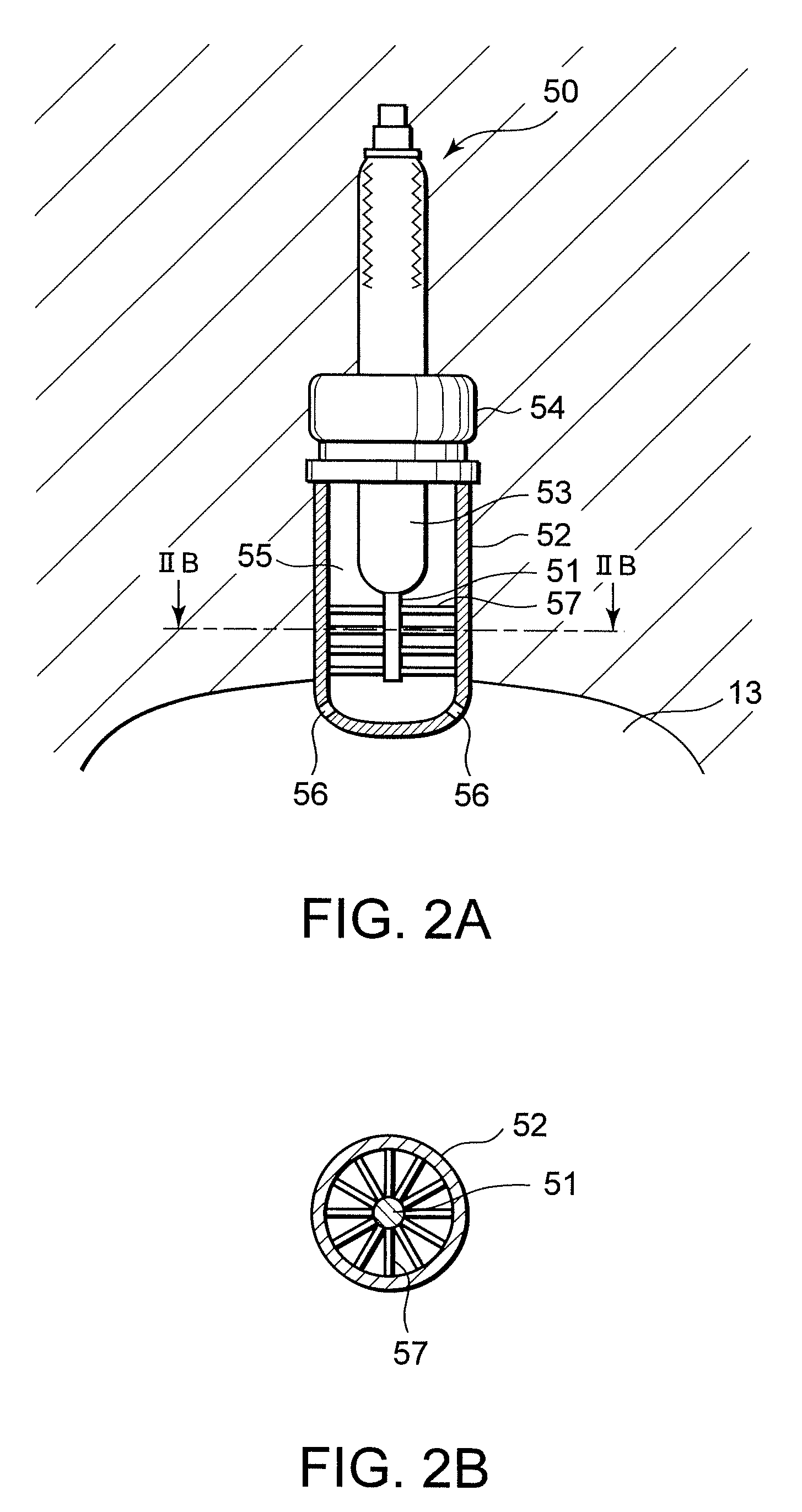
[0031]this invention will be described with reference to FIG. 1, FIGS. 2A and 2B, FIG. 3, and FIGS. 4A-4D.
[0032]Referring to FIG. 1, a non-equilibrium plasma discharge type vehicle internal combustion engine 100 for a vehicle comprises a cylinder block 10, and a cylinder head 20 provided on the upper side of the cylinder block 10. The internal combustion engine 100 is a four-stroke-cycle multi-cylinder engine.
[0033]A cylinder 12 is formed in the cylinder block 10 to accommodate a piston 11. A main combustion chamber 13 is formed by a crown surface of the piston 11, a wall surface of the cylinder 12, and a bottom surface of the cylinder head 20. When fuel mixture burns in the main combustion chamber 13, the piston 11 reciprocates within the cylinder 12 under a combustion pressure.
[0034]An intake port 30 for supplying fuel mixture to the main combustion chamber 13 and an exhaust port 40 for expelling exhaust gas from the main combustion chamber 13 are formed in the cylinder head 20.
[0...
PUM
 Abstract
Description
Claims
Application Information