Apparatus and method for aeration/mixing of water

a technology for aerating apparatus and water, which is applied in the direction of mixers, heating types, fuel gas production, etc., can solve the problems of clogging the use of water, reducing the efficiency of aeration apparatus, so as to prevent the falling of sludge and improve the performance of the apparatus. , the effect of efficient circulation

Inactive Publication Date: 2010-01-12
WATERIX
View PDF21 Cites 10 Cited by
  • Summary
  • Abstract
  • Description
  • Claims
  • Application Information

AI Technical Summary

Benefits of technology

[0018]When the water is taken into the apparatus from the bottom of the basin and returned back to the surface of the basin, the water of the basin will be efficiently circulated and the incoming water is as oxygen-poor as possible. This fact essentially increases the performance of the apparatus. In other aeration apparatuses, the oxygen content of the water coming to the aeration apparatus is of average level or the apparatus circulates the same relatively oxidized water. At the same time as the apparatus oxidizes efficiently, it circulates the water of the basin thereby preventing the falling of the sludge to the bottom. Thereby, there is no need for separate mixers.
[0019]As a summary, it may be stated that by calculating the oxidation efficiency of our test apparatus, one is ended up to an efficiency of 6.0 kg O2 / kWh for an apparatus of the invention in large scale. The energy saving is considerable.
[0027]An external fastening of the cover prevents contamination and clogging of the nozzle and nozzle opening

Problems solved by technology

This phenomenon might lead to oxygen depletion, death of fish and a final pollution of the lake.
The main drawback with these devices is their contamination and clogging in use.
The aeration causes ca 80% of the energy costs of a waste water treatment plant (i.e. an activated sludge plant, i.e. a plant using biological treatment) and this electricity consumption corresponds to ca 30% of the operational costs of the waste water treatment plant.
The maintenance of a bottom aerator is difficult.
In addition, the service is expensive and takes several weeks.
This, in turn, increases the investments and number of objects to be maintained.
The bottom aerators gradually become clogged and their result worsens, especially if the aeration is often interrupted.
This increases both investments and operational costs.
The problem with surface aerators is the bad efficiency of the oxidation, the weak adjustability and the fact that the basin has to be rather low.
A typical depth is 3.5 m, which makes the surface of the basins large and neither is their form optimal (expensive to make).

Method used


Image

  • Apparatus and method for aeration/mixing of water
  • Apparatus and method for aeration/mixing of water
  • Apparatus and method for aeration/mixing of water

Examples


Embodiment Construction

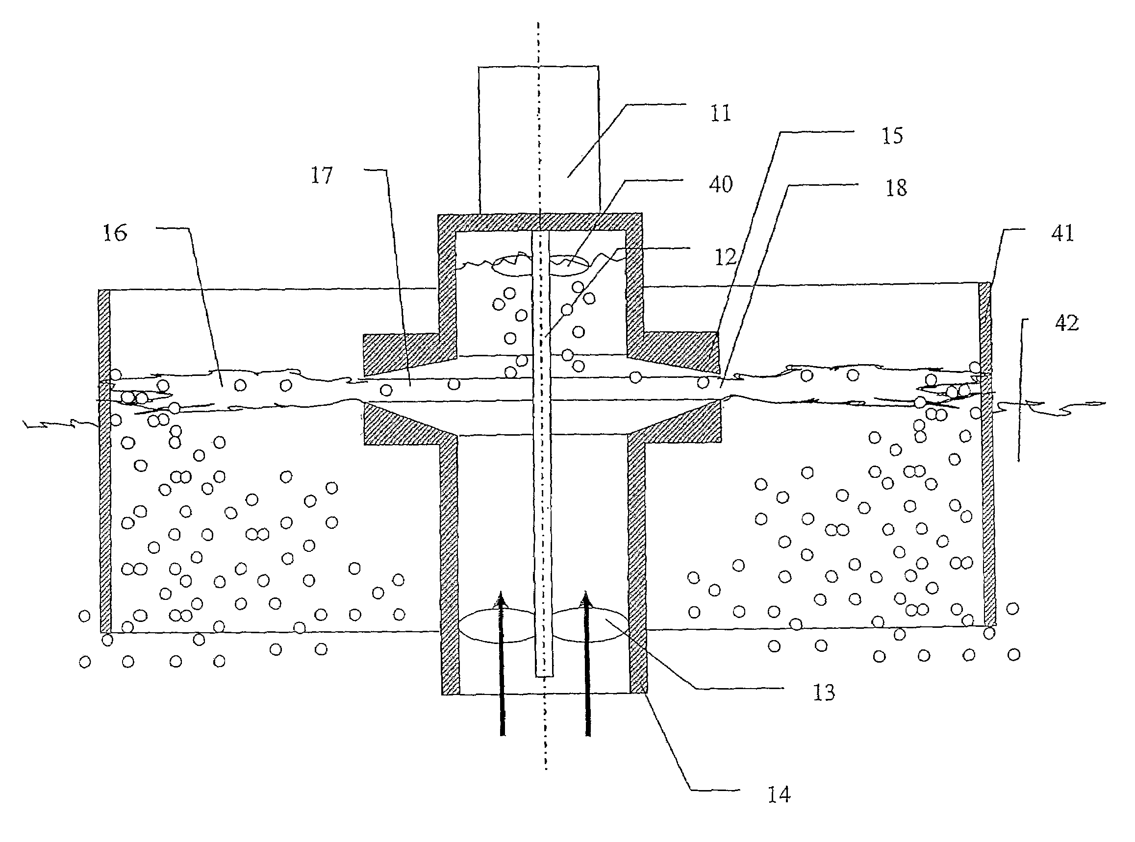
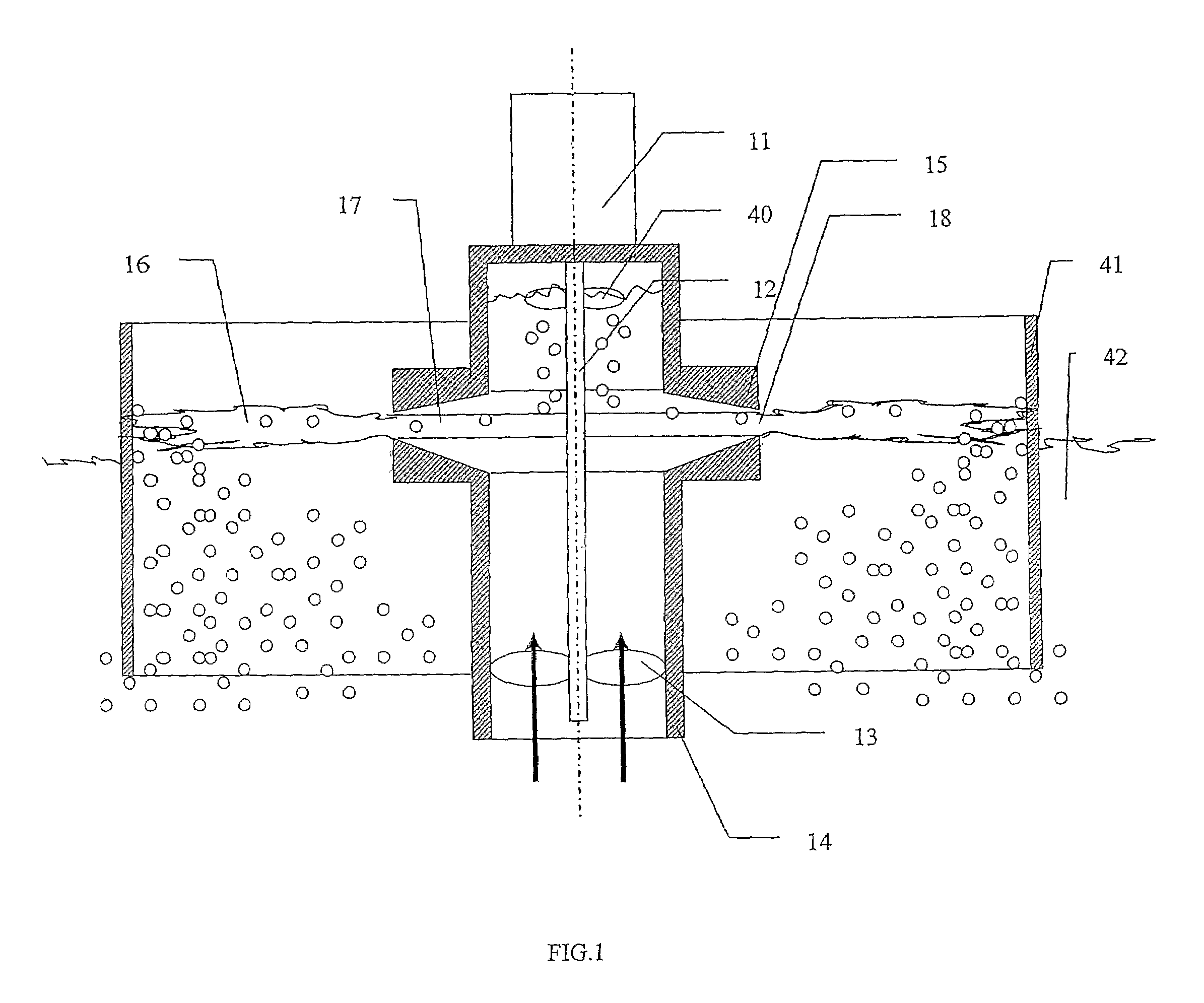
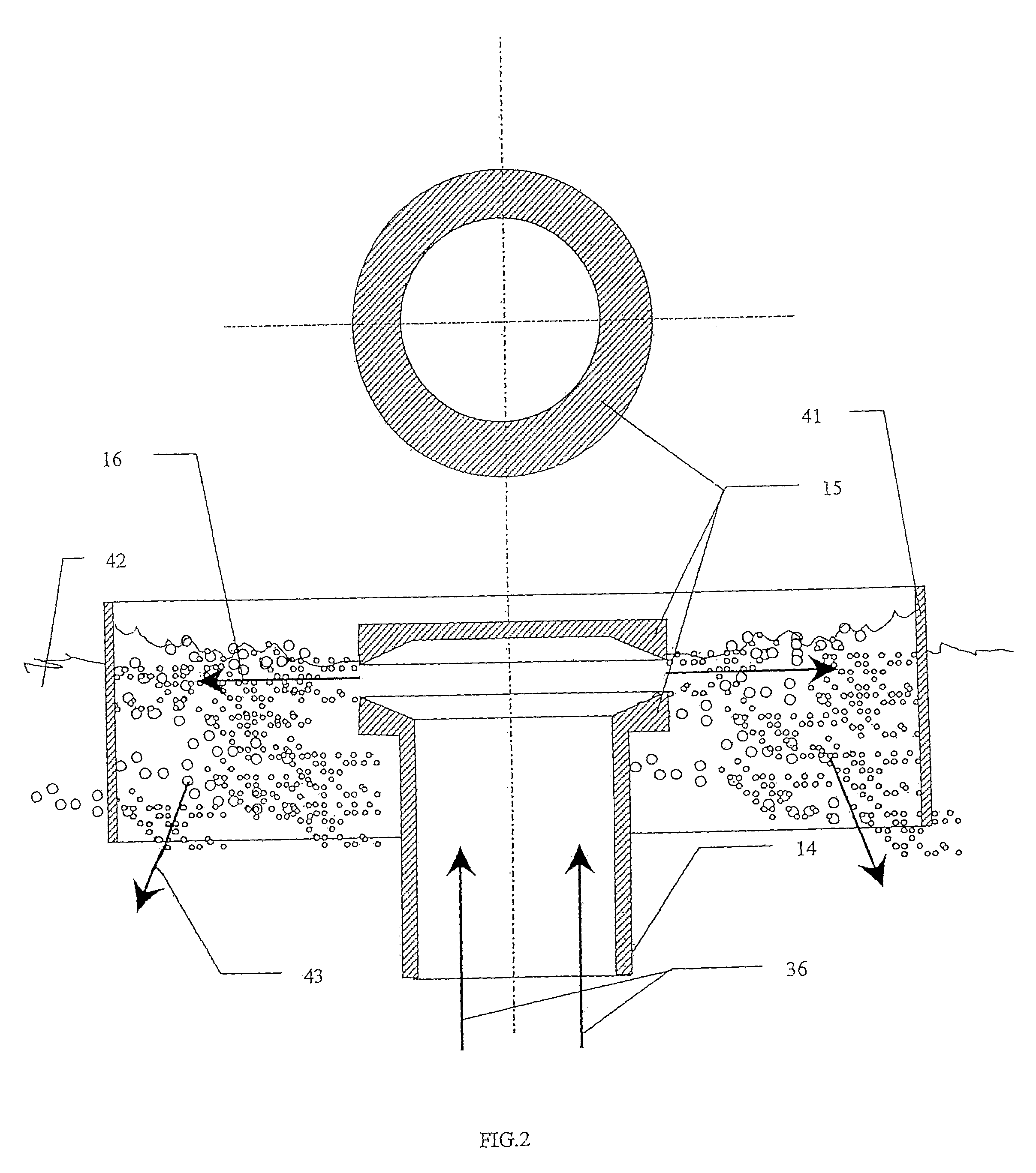
[0038]FIG. 1 presents a cross-sectional view of the apparatus of the invention, in which water is aerated in a basin. The feed pipe therein has been marked with reference number 14. There is a propeller 13 in the feed pipe, which propeller is connected to a motor 11 by means of an axle 12. The propeller pump consists of the motor 11, an axle 12 between the propeller and the motor and of a propeller 13. In the upper end of the feed pipe 14, the water is branched into horizontal nozzle rings 15, the construction of which is such that the inlet consists of conical nozzles 17, which end up to an annular nozzle opening 18. The conical nozzle ends up to a nozzle opening and is abruptly expanding thereafter. An ejector is hereby achieved. The construction between the nozzle rings 15 works as an ejector and causes a water jet 16, which sucks air in itself above and beneath the jet. The water is aerated, the air is efficiently mixed with the water jet and is returned back to the basin. There...


PUM

PropertyMeasurementUnit
depthaaaaaaaaaa
heightaaaaaaaaaa
lengthaaaaaaaaaa

Abstract

The aeration system is for aeration and / or mixing of water, which system has at least one aeration unit that has a pump / propeller inside a feed pipe. The feed pipe, to which the water to be aerated, is sucked from beneath. The aeration system has the feed pipe expanding in the upper part of the aeration unit to a conical space working as a nozzle, via which the water continues its way to at least one annular opening.

Description

PRIOR APPLICATIONS[0001]This is a US national phase patent application that claims priority from PCT / FI2005 / 000051, filed 26 Jan. 2005, that claims priority from Finnish Patent Application No. 20040113, filed 27 Jan. 2004.TECHNICAL FIELD[0002]The invention is concerned with an aeration system and method for mixing and / or aeration of water.BACKGROUND ART[0003]Biological treatment is an important phase in the treatment of wastewaters and it is also the phase consuming most energy. In biological treatment carried out by means of aeration, it is necessary to continuously feed oxygen into the water in order to enable bacterial activity in the process. The oxygen concentration decreases also in natural waters during the long winter season, when the ice covering prevents a natural oxidation through the air. This phenomenon might lead to oxygen depletion, death of fish and a final pollution of the lake. Biological treatment is also used for e.g. removal of gases, such as radon, from the wat...

Claims


Application Information

Patent Timeline
Patent Type & Authority Patents(United States)
IPC IPC(8): B01F3/04B01F5/02B01F15/00
CPCB01F3/04758B01F3/04773B01F5/0268B01F15/00025B01F2215/0052B01F2215/045B01F2215/0463B01F23/23413B01F23/23421B01F25/25B01F35/1452B01F2101/305
Inventor HUHTA-KOIVISTO, RISTOHUHTA-KOIVISTO, ESKO
Owner WATERIX
Why Eureka
Try Eureka