
Construction machine for machining floor surfaces

Active Publication Date: 2010-01-12
WIRTGEN AMERICA
View PDF11 Cites 39 Cited by
  • Summary
  • Abstract
  • Description
  • Claims
  • Application Information

AI Technical Summary

Benefits of technology

[0005]It is an object of the invention to improve a construction machine of the initially mentioned type in such a manner that an exchange of the tools can be performed with reduced expenditure in personnel and time and with a reduced risk of accidents.
[0008]The invention makes it advantageously possible to reduce the required time for the exchange of tools because the auxiliary drive can be actuated by the operating person at the site of work roller. The feature that the auxiliary drive will drive the work roller with low power, nearly completely excludes the danger of accidents caused by the possibility that parts of the clothes of the operating person might get caught in the tools of the work roller during rotation of the latter. Since the torque of the auxiliary drive is just high enough to allow for a rotational movement of the work roller with about 3 rpm, the motor of the auxiliary drive can be quickly stopped in case that higher forces should occur on the work roller. Further, the auxiliary drive is arranged to stop automatically after about 4 seconds subsequent to each activation.
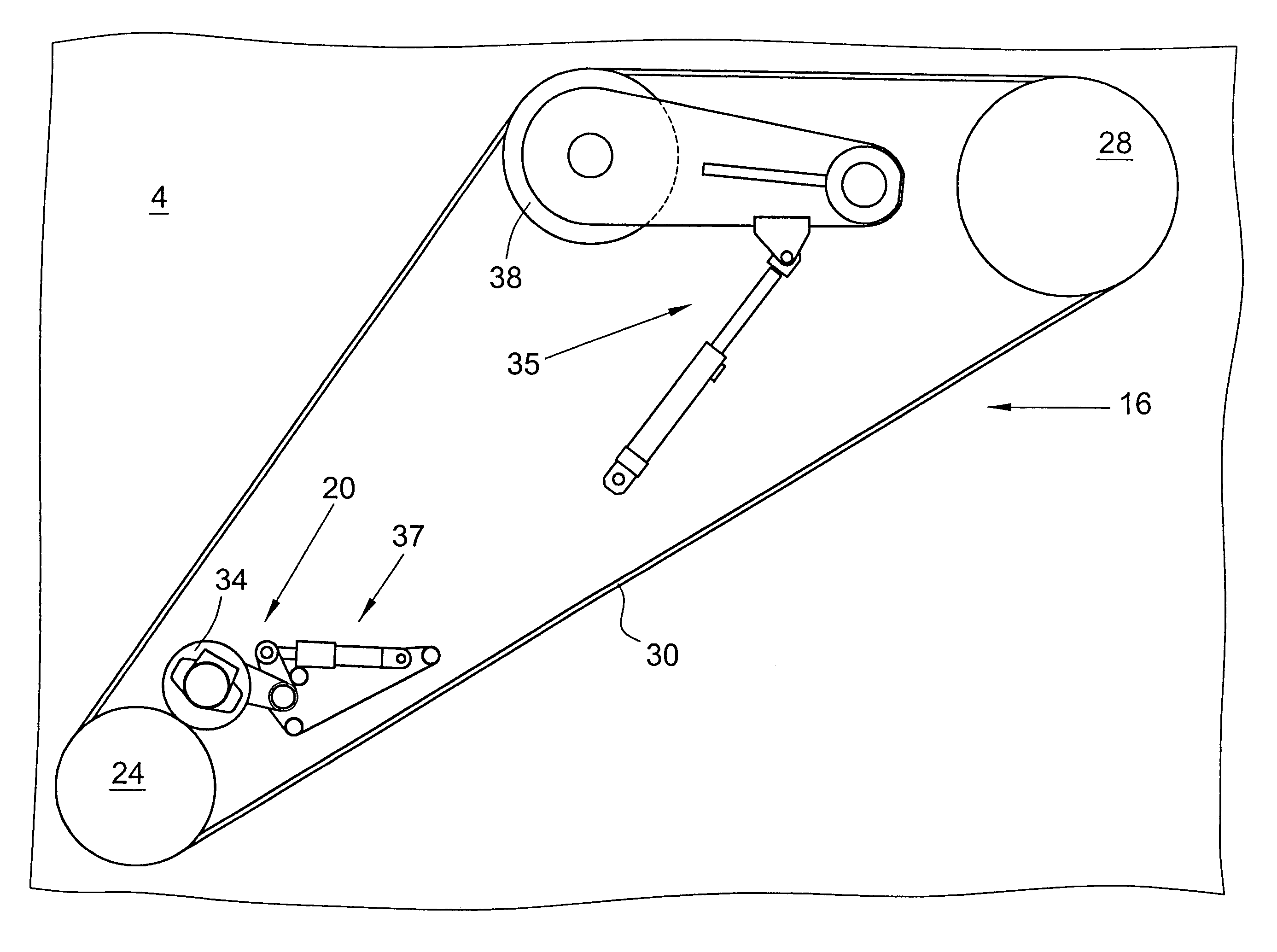
[0009]Preferably, it is provided that the transmission arranged between the work motor and the work roller comprises a belt drive with at least two pulleys and at least one drive belt, and that the auxiliary drive can be coupled to the belt drive. In a belt drive, the auxiliary drive can be advantageously coupled in such a manner that no enlargement of the width of the construction machine is required. Notably, the auxiliary drive can be accommodated within the housing of the belt drive so that the construction machine need not have a larger width.
[0010]It can be provided that the motor-side pulley of the belt drive can be decoupled from the drive motor by means of a coupling unit. In this manner, the flux of force between the drive motor and the work roller can be reliably interrupted.
[0012]In this arrangement, the friction roller can be arranged to be coupled to the drum-side pulley. The use of a friction roller further offers the advantage that the torque which can be transmitted is limited. If there is a too high moment of resistance, e.g. in case of a blockade of the work drum, the friction roller will slip, thus considerably reducing the risk of accidents because no high forces can occur during the rotation of the work drum. This is of importance e.g. if pieces of clothing of the operating person get caught on the tools of the work drum while the drum is rotated.

Problems solved by technology

In case of extremely hard road surfaces, it may happen that the tools have a service life as brief as only half an hour and that all of the tools of the milling drum have to be replaced thereafter.
This rotation can be carried out by hand, which, however, requires considerable forces.

Method used


Image

  • Construction machine for machining floor surfaces
  • Construction machine for machining floor surfaces
  • Construction machine for machining floor surfaces

Examples


Embodiment Construction

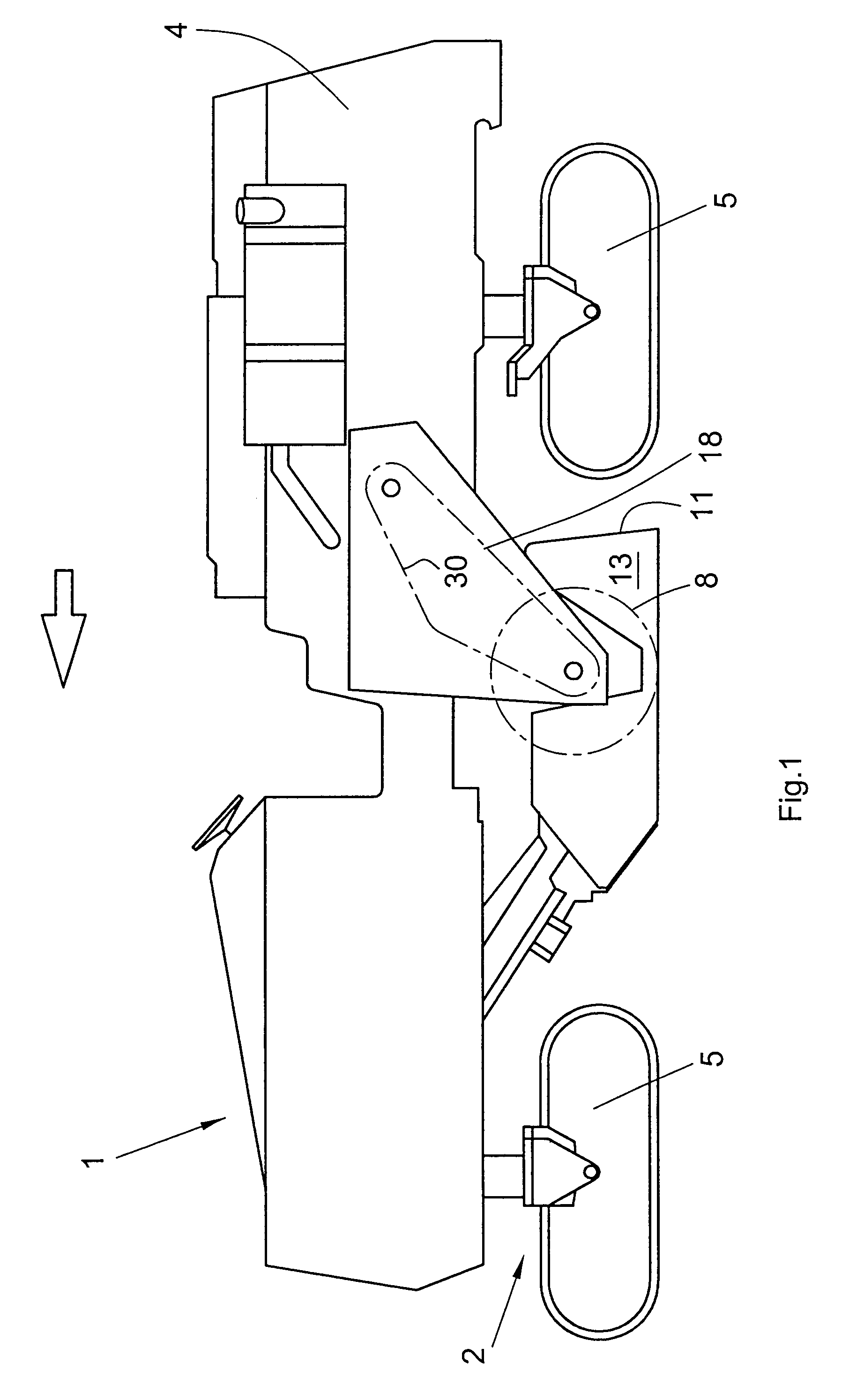
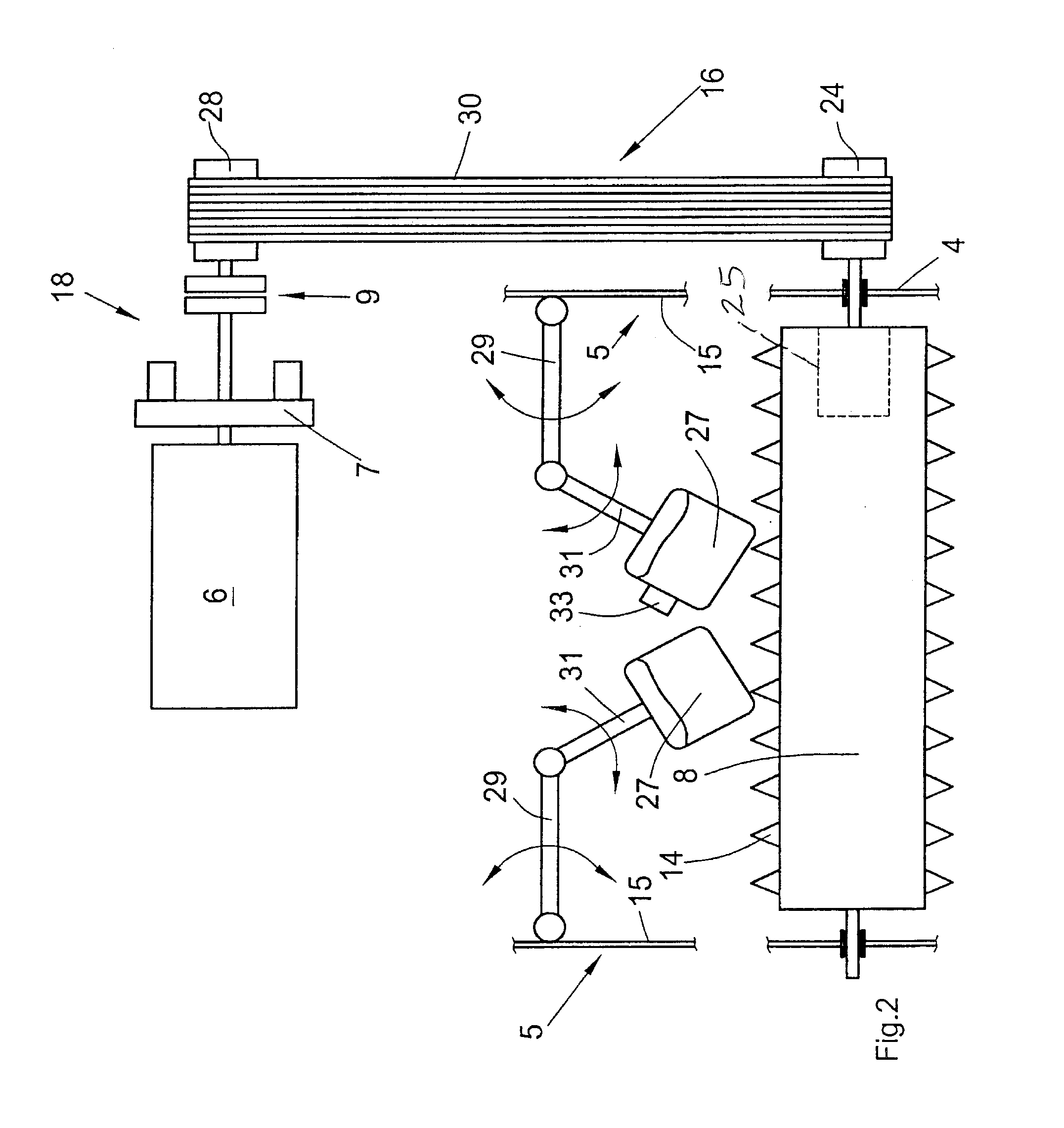
[0032]The construction machine 1 illustrated in FIG. 1 is a large-sized milling device comprising a machine frame 4 supported by truck assemblies 5 of a chassis 2 which is adjustable in height. Machine frame 4 is provided with a work drum 8, arranged between the truck assemblies 5 and supported on machine frame 4, which work drum is equipped with tools 14 formed as milling bits for removing a road surface. The exchangeable tools 14 are arranged in a predetermined pattern on the outer surface 12 of work drum 8. A drive line 18 is provided to drive the work drum 8. Drive line 18 comprises at least one drive motor 6 as well as a belt drive 16 coupled to drive motor 6. Belt drive 16 comprises a motor-side pulley 28 and a drum-side pulley 24 which are coupled to each other by at least one drive belt 30. Drive belt 30 is preferably composed of V-belts.

[0033]FIG. 2 shows the drive line comprising the drive motor 6 which can be coupled to a pump distributor drive system 7 arranged to have c...


PUM

PropertyMeasurementUnit
Fractionaaaaaaaaaa
Fractionaaaaaaaaaa
Electrical resistanceaaaaaaaaaa

Abstract

In a construction machine 1 for the treatment of ground surfaces, comprising a chassis 2 carrying a machine frame 4, a drive motor 6, a work drum 8 supported on the machine frame 4 and having exchangeable tools 14 fastened to its outer surface 12, and a drive line 18 for the work drum 8 comprising at least the drive motor 6 and a transmission coupled to the drive motor 6, it is provided that an auxiliary drive 20, adapted to be coupled to the drive line 18, is arranged to rotate the work drum 8 in the raised condition of the drum by a predetermined or selectable rotational angle, the torque of the auxiliary drive 20 being higher than the moment of inertia of the work drum 8 and of the drive line 18 in the switched-off or decoupled state of the drive motor 6.

Description

BACKGROUND OF THE INVENTION[0001]The invention relates to a construction machine for the treatment of ground surfaces.[0002]Construction machines of this type, e.g. large-sized milling devices or cold milling devices, comprise a machine frame having supported therein a milling drum extending transversely to the moving path to be treated. The machine frame further accommodates the milling-drum drive unit and is supported, in a manner allowing for height adjustment, by a plurality of truck assemblies arranged before and behind the milling drum.[0003]Such large-sized milling device and cold milling devices, or recyclers, are used for the milling of road surfaces, e.g. on highways or country roads. The milling drums have their outer surfaces equipped with exchangeable tools. In case of extremely hard road surfaces, it may happen that the tools have a service life as brief as only half an hour and that all of the tools of the milling drum have to be replaced thereafter. For this purpose,...

Claims


Application Information

Patent Timeline
IPC IPC(8): E21C25/00E01C23/088
CPCE01C23/088E01C23/127Y10T29/49826
Inventor BUSLEY, PETERGAERTNER, OLAFSIMONS, DIETER
Owner WIRTGEN AMERICA
Learn More