Optical fiber cable having raised coupling supports

a technology of optical fiber cable and coupling support, which is applied in the field of optical fiber cable, can solve the problems of optical fiber force development, signal attenuation or signal loss, microbending and macrobending effects, etc., and achieve the effect of reducing cable costs and limiting the amount of compressive conta

Inactive Publication Date: 2010-01-12
DRAKA COMTEQ BV
View PDF22 Cites 108 Cited by
  • Summary
  • Abstract
  • Description
  • Claims
  • Application Information

AI Technical Summary

Benefits of technology

[0019]The design of the coupling element layer thus serves to couple the optical fiber element to the buffer tube at discrete contact points, thereby limiting the amount of compressive contact on the optical fiber elements. Compression, of course, can lead to optical signal losses. In this way, the design of the coupling element according to the present invention limits the occurrence of the kinds of unwanted pressures that can cause microbending or macrobending in the optical fiber element.
[0020]In brief, the design of the coupling element couples the optical fiber element to the buffer tube without employing a compressive, frictional cushioning layer. Further, in some instances the buffer tube structure according to the present invention can reduce cable costs by eliminating the use of conventional cushioning layers; only the raised members of this coupling element are used to support the optical fiber element rather than the entire surface of a cushioning layer. Additionally, the invention may incorporate water-blocking materials (e.g., super-absorbent polymers) to eliminate the need for a separate water-blocking layer.

Problems solved by technology

First, forces may develop on the optical fibers due to contact with rough, hard, or uneven surfaces within the optical fiber cables.
Such contact, for example, may result from thermal cable expansion or contraction, which can cause microbending and macrobending effects.
This, in turn, can lead to signal attenuation or signal loss.
Not only can these effects hamper accessibility to the fibers during connection operations (e.g., splicing), but also insufficient coupling can lead to excess and / or unevenly distributed optical fiber length (e.g., optical fibers accumulating in a confined space).
Such accumulation may cause bending or otherwise force contact between the optical fibers and other cable elements, which can likewise lead to microbending and macrobending.
If water intruding into the cables can spread (e.g., flow) along the length of the cables to these electronic devices, severe damage to the electronic systems may result.
The addition of these layers, however, can lead to larger cables, which are not only more costly to produce and store but also heavier, stiffer, and thus more difficult to install.
That usefulness notwithstanding, such thixotropic filling greases are relatively heavy and messy, thereby hindering connection and splicing operations.
Unfortunately, in practice, the water-swellable elements used in these designs may not provide for sufficient coupling of the optical fibers to the buffer tube.
Although frictional coupling is effective in preventing relative movement between the optical fibers and the buffer tube, the optical fibers may experience microbending or macrobending when the buffer tube contracts due to cooling.
This may result in optical signal attenuation or signal loss.
Further, the coupling pressure exerted on the optical fibers by the foam cushioning may diminish over time due to the relaxation or degradation of the polymeric foam.

Method used


Image

  • Optical fiber cable having raised coupling supports
  • Optical fiber cable having raised coupling supports
  • Optical fiber cable having raised coupling supports

Examples


Embodiment Construction

[0026]The present invention is described herein with reference to the accompanying drawings. As will be appreciated by those having ordinary skill in the art, these drawings are schematic representations, which are not necessarily drawn to scale. This invention may be embodied in many different forms and should not be construed as limited to the embodiments set forth herein. The embodiments disclosed are provided to convey the scope of the invention to those having skill in the relevant art.

[0027]In one aspect, the invention embraces an optical fiber cable that provides satisfactory coupling of optical fibers and a surrounding buffer tube but in a way that reduces unwanted microbending and macrobending effects. In another aspect, the invention embraces methods of making such optical fiber cables.

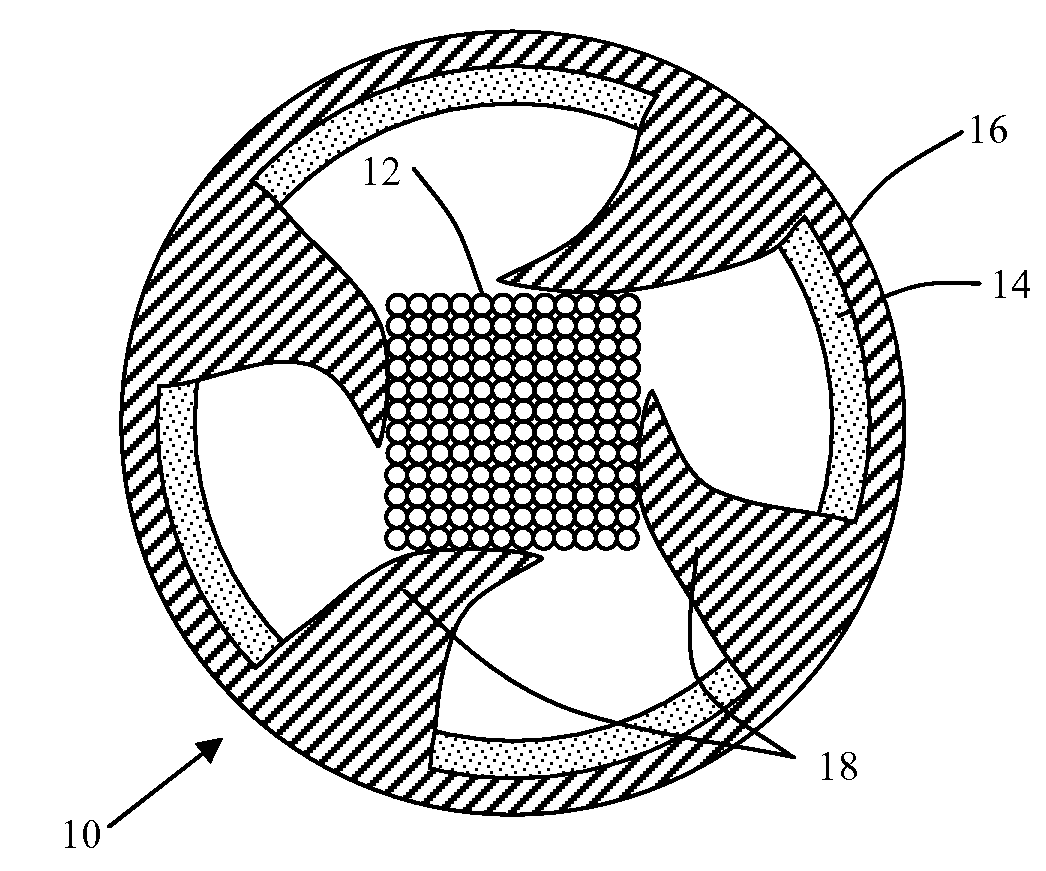
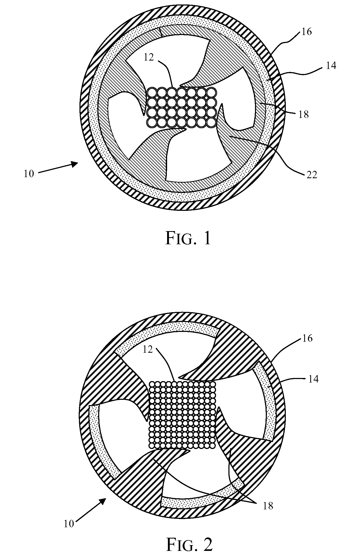
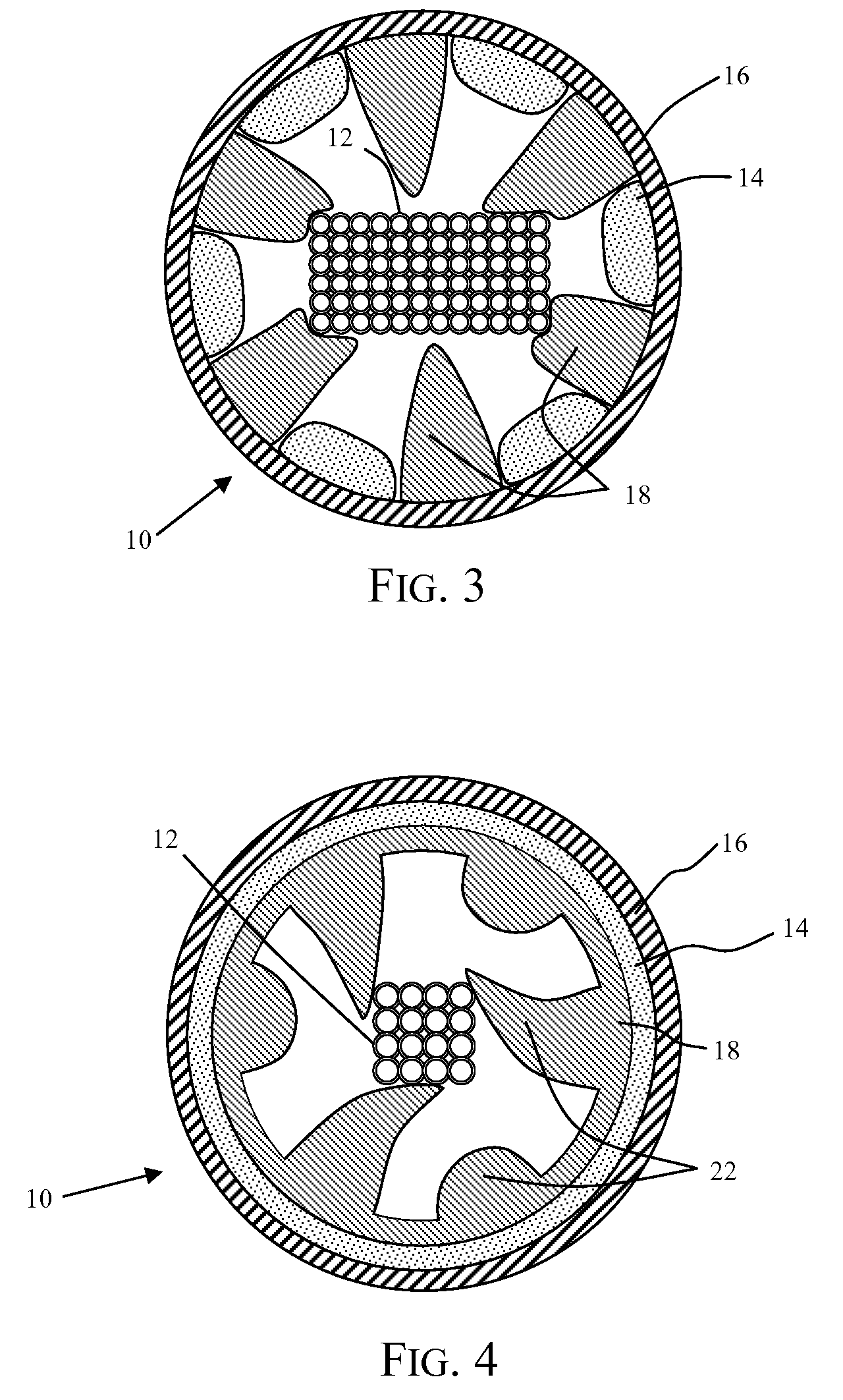
[0028]FIG. 1 depicts a cross-sectional view of one embodiment of an optical fiber cable 10 according to the present invention. In this exemplary embodiment, an optical fiber element 12 is di...


PUM

PropertyMeasurementUnit
tensile strengthaaaaaaaaaa
elongation to breakaaaaaaaaaa

Abstract

Disclosed is an optical fiber cable that includes optical fibers and a deformable coupling element enclosed within a buffer tube. The coupling element is formed from a deformable yet substantially incompressible material and features a number of raised members projecting toward the optical fibers. The design of the coupling element layer permits coupling of the optical fibers to the buffer tube without the use of a compressive cushioning layer. This arrangement distributes the compressive force applied to discrete points along the outer perimeter of the optical fiber element.

Description

CROSS-REFERENCE TO PRIORITY APPLICATION[0001]This application hereby claims the benefit of U.S. Provisional Patent Application Ser. No. 60 / 946,752, for Optical Fiber Cable Having Raised Coupling Supports (filed Jun. 28, 2007) via 35 U.S.C. § 119. U.S. Provisional Patent Application Ser. No. 60 / 946,752 is hereby incorporated by reference in its entirety.FIELD OF THE INVENTION[0002]The invention relates to an optical fiber cable that contains optical fibers inside a buffer tube.BACKGROUND[0003]Optical fiber cables are used to transmit information including telephone signals, television signals, data signals, and Internet communication. To preserve the integrity of the signal transported by optical fiber cables, certain design factors warrant consideration.[0004]First, forces may develop on the optical fibers due to contact with rough, hard, or uneven surfaces within the optical fiber cables. Such contact, for example, may result from thermal cable expansion or contraction, which can c...

Claims


Application Information

Patent Timeline
Patent Type & Authority Patents(United States)
IPC IPC(8): G02B6/44
CPCG02B6/4403G02B6/4429
Inventor PARRIS, DON
Owner DRAKA COMTEQ BV
Why Eureka
Try Eureka