Method and an injection nozzle for interspersing a gas flow with liquid droplets

a gas flow and liquid drop technology, applied in the direction of air transportation, engine fuction, lighting and heating apparatus, etc., can solve the problems of gas turbine blade contamination, loss of efficiency and power of the whole installation of up to approx, and simple methods that are not suitable for modern turbines, etc., to achieve the effect of improving the interspersed gas flow and a wide range of distribution

Inactive Publication Date: 2010-01-19
TURBOTECT
View PDF11 Cites 9 Cited by
  • Summary
  • Abstract
  • Description
  • Claims
  • Application Information

AI Technical Summary

Benefits of technology

[0032]This and other advantageous effects results in that at least a portion of the liquid droplets intersperse the gas flow much more efficiently than without an auxiliary gas.
[0033]According to the invention a relatively broad distribution range (e.g. Gauss distribution) of different droplet diameters, for example between 50 and 250 μm is strived for. Liquid droplets of different diameters will have different trajectories and thus penetrate to different extent into the gas flow, resulting in an improved interspersion of the gas flow with the liquid droplets.

Problems solved by technology

All gas turbines suffer from contamination of the compressor blades.
The contamination of the compressor blades leads to losses in the efficiency and power of the whole installation of up to approx.
These simple methods however are not suitable for modern turbines, particularly for those whose compressor blades are provided with protective coatings and whose combustion chamber as well as turbine blade cooling systems are provided with the most modern technology.
It however has the disadvantage that it needs to be carried out with the turbine at standstill and thus causes losses in production.(iii) The on line wet-cleaning method (i.e. wet cleaning during operation) with the cleaning liquids as stated under (ii).
For such large high-power output gas turbines the injection nozzles disclosed in U.S. Pat. No. 5,193,976 are no longer performing adequately in order to achieve an efficient and uniform interspersion of the air cross section at the injection plane.
By way of this an efficient interspersion of the whole intake air flow with the liquid droplets becomes very difficult.
They are however not suitable for the application for wet-cleaning a large gas turbine compressor where the speed of the intake air at the injection location is approx.
The extremely finely atomised droplets may either not penetrate the boundary layer or are immediately deflected by the airflow resulting in a very poor interspersion of the airflow and thus a poor wetting of the blade surfaces.
This portion of the liquid may not be used for the cleaning and may cause erosion problems, mainly on the first compressor rotor blade row.
To conclude, it may be said that on the one hand the two-substance nozzles known from the state of the art are designed for very different applications and thus are not suitable for interspersing strong, high velocity gas flows with liquid droplets.

Method used


Image

  • Method and an injection nozzle for interspersing a gas flow with liquid droplets
  • Method and an injection nozzle for interspersing a gas flow with liquid droplets
  • Method and an injection nozzle for interspersing a gas flow with liquid droplets

Examples


Embodiment Construction

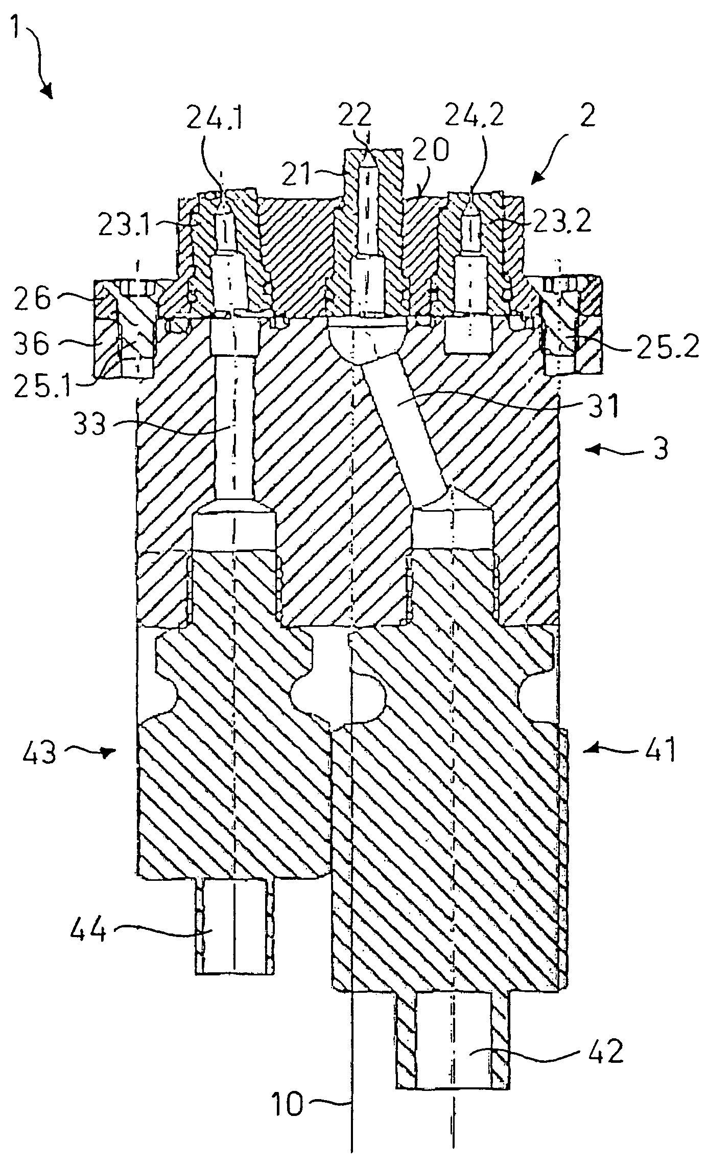
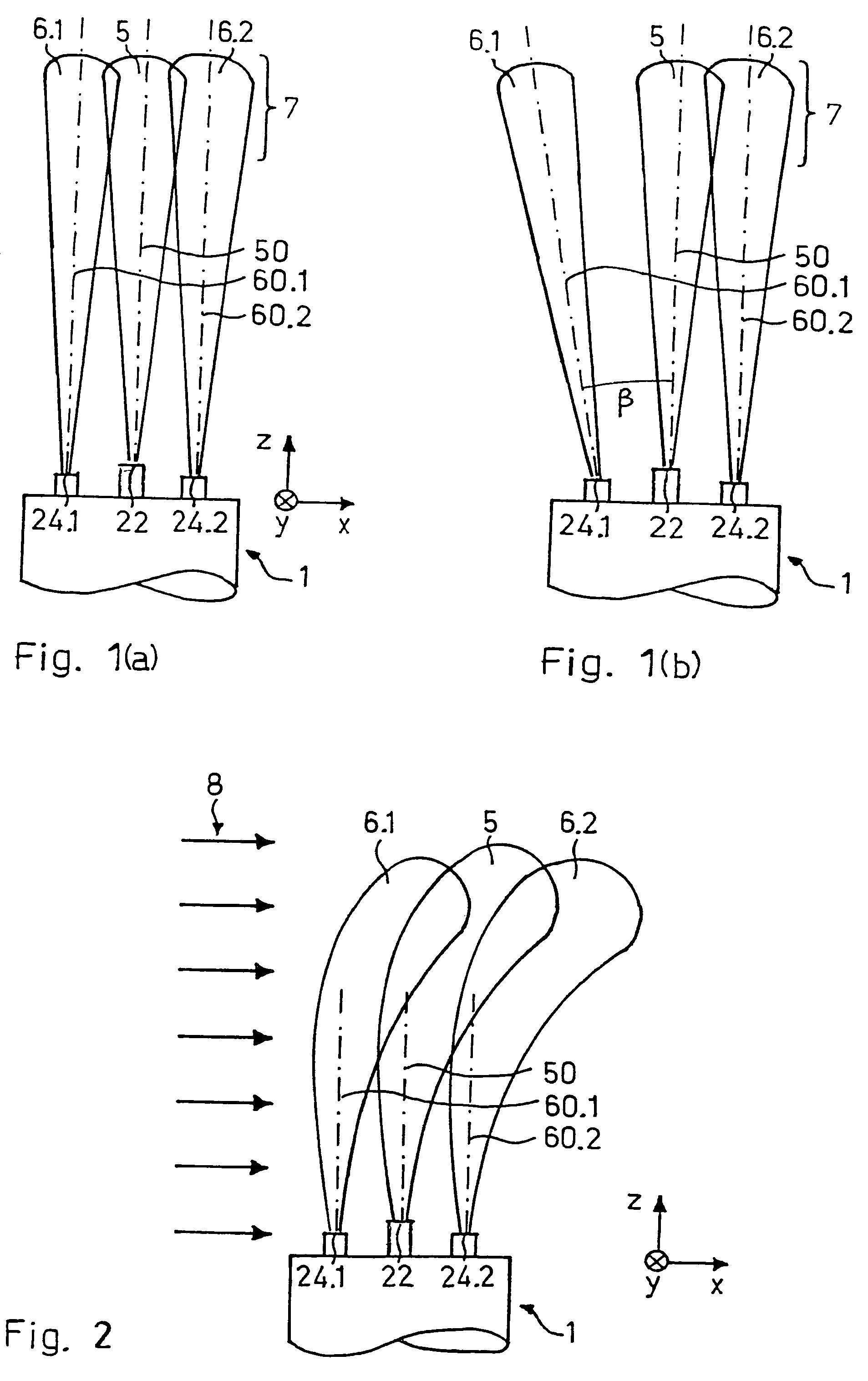
[0045]In FIG. 1(a) the upper part of a first embodiment form of an injection nozzle 1 according to the invention is represented schematically in a lateral view. In this representation and for didactic reasons it is firstly assumed that no gas flow is present. Liquid droplets 5 are discharged from a liquid orifice 22 of the injection nozzle 1, and specifically in a manner such that the liquid droplets 5 are discharged in essentially one plane (yz-plane)—here called the liquid injection plane 50. One may in terms speak of a “plane” here since the extension of the spatial liquid droplet distribution in the x-direction is much smaller than in the y- respectively the z-direction. This fact is not immediately evident from the representation in the FIGS. 1-3, since in these, for the sake of clarity, the length conditions in the three spatial directions are not represented exactly true to scale.

[0046]Furthermore an auxiliary gas 6.1, 6.2 is discharged respectively from at least one gas orif...


PUM


Abstract

In the method for interspersing a gas flow with liquid droplets, the liquid droplets are injected in a liquid injection plane into the gas flow, characterized in that an auxiliary gas is simultaneously injected with the liquid droplets into the gas flow. The injection speed of the auxiliary gas is larger than the injection speed of the liquid droplets so that the injected auxiliary gas stabilizes the injected liquid droplets with respect to trajectory and size, partly shields them from the gas flow and / or entrains them into the gas flow. By way of this one achieves an improved control of the spatial distribution of the liquid droplets and their size distribution. The liquid droplets penetrate the gas flow more efficiently than without an auxiliary gas. A preferred use is the online wet-cleaning of a gas turbine compressor.

Description

CROSS-REFERENCE TO RELATED APPLICATIONS[0001]This application is a divisional application under §1.53(b) of prior application Ser. No. 10 / 490,262 filed Mar. 22, 2004 now U.S. Pat. No. 7,114,910; which was a §371 national phase filing of PCT / CH03 / 00765 filed Nov. 19, 2003, and claims priority to Swiss application No. 0104 / 03 filed Jan. 24, 2003 and to Swiss application No. 1453 / 03 filed Aug. 26, 2003.FIELD OF THE INVENTION[0002]The present invention relates to a method for interspersing a gas flow with liquid droplets, according to the preamble of the first patent claim. One of its preferred applications lies in the field of industrial gas turbines where it may be used for wet-cleaning a gas turbine compressor. The invention also relates to an injection nozzle for carrying out the method, according to the preamble of a further independent patent claim. The invention further relates to a turbo-machine, e.g. a gas turbine compressor, according to the preamble of a further independent p...

Claims


Application Information

Patent Timeline
Patent Type & Authority Patents(United States)
IPC IPC(8): F01D1/00B05B1/30B05B7/00B05B7/08B05B17/06F01D25/00F04D29/70
CPCB05B1/3013B05B7/0075B05B7/08F01D25/002F04D29/705B05B17/0607F05D2260/212Y02T50/676Y02T50/60
Inventor STALDER, JEAN-PIERRE
Owner TURBOTECT
Why Eureka
Try Eureka