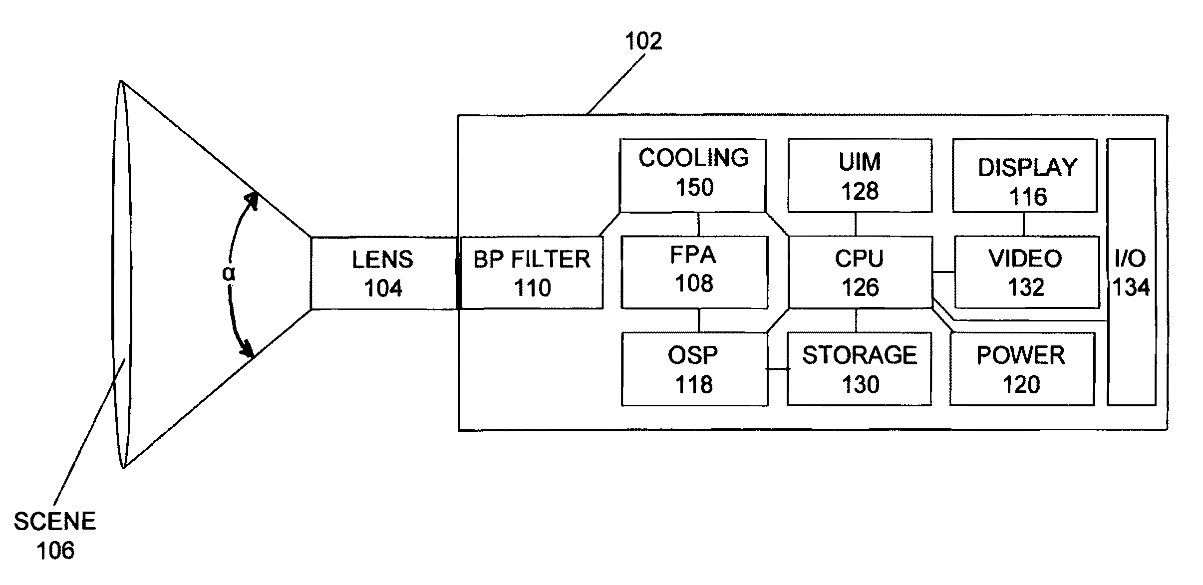
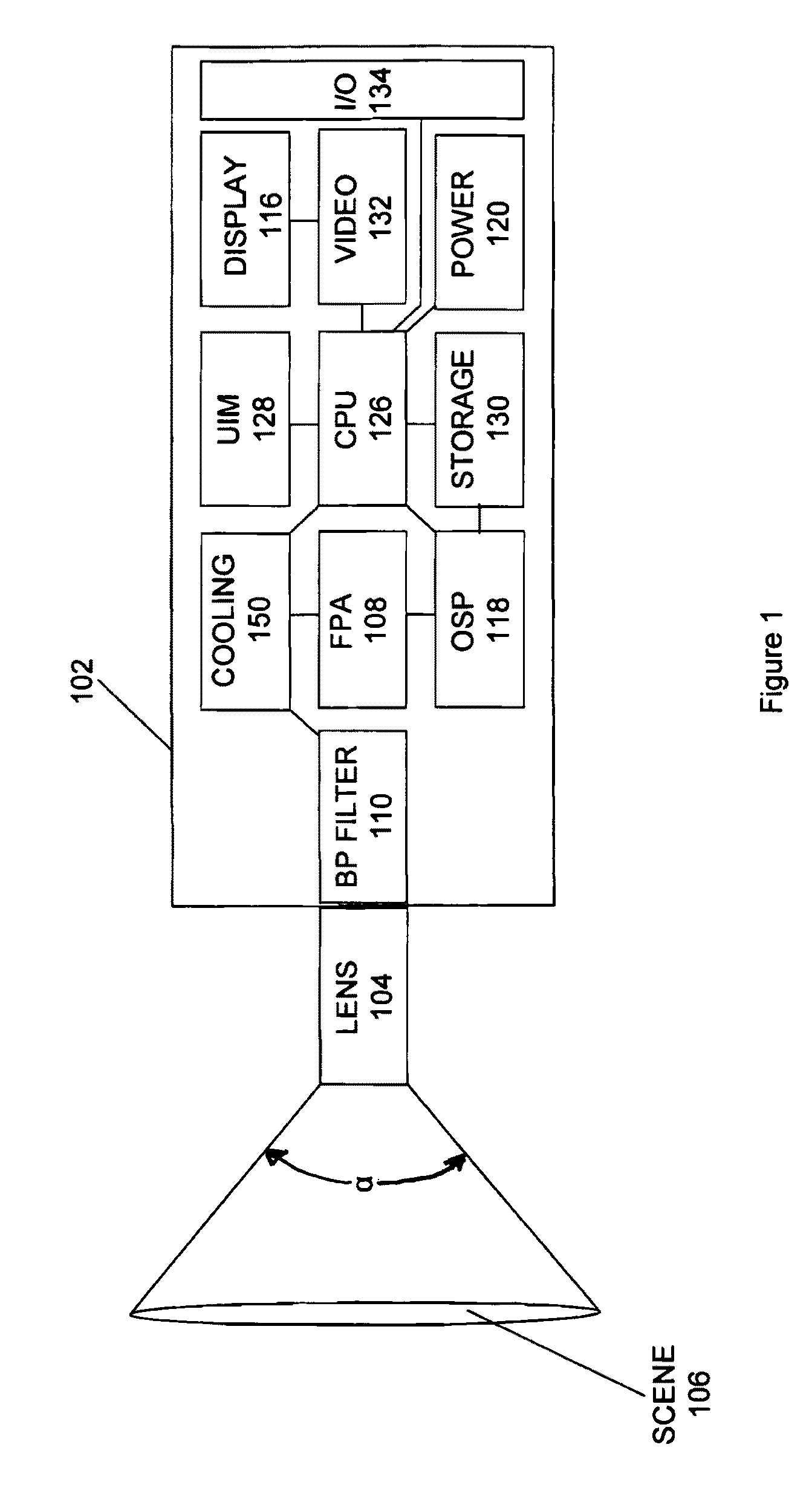
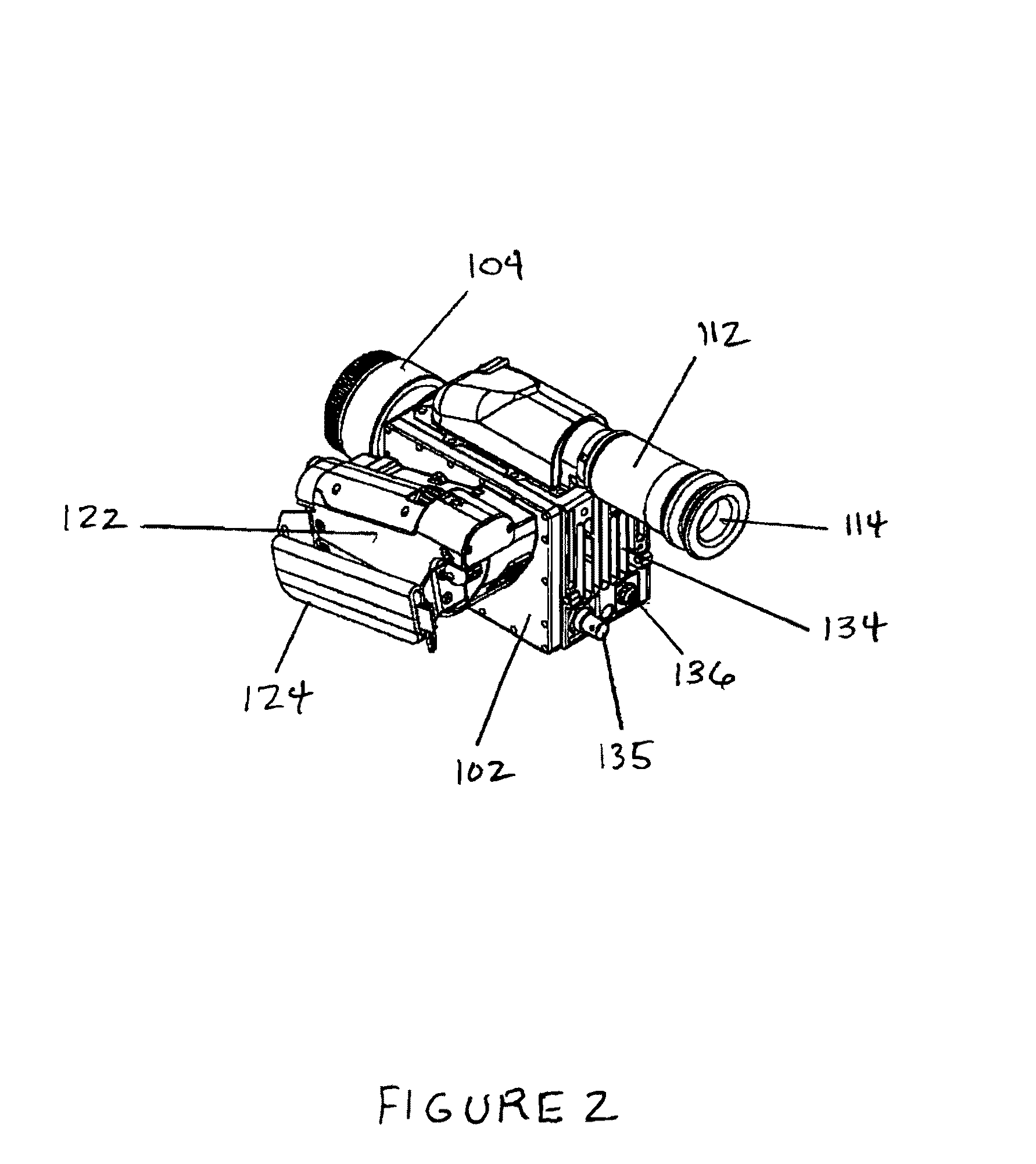
Thermography camera configured for gas leak detection

a technology of thermal imaging camera and gas leak detection, which is applied in the field of infrared video camera system, can solve the problems of limiting the distance over which the illuminator can effectively illuminate a scene, the inability to view gas plumes, and the additional cost and complexity of including an illuminator in the video camera system, so as to limit the spectral bandwidth of the scene image

Active Publication Date: 2010-01-19
TELEDYNE FLIR LLC
View PDF30 Cites 50 Cited by
  • Summary
  • Abstract
  • Description
  • Claims
  • Application Information

AI Technical Summary

Problems solved by technology

These include the inability to view gas plumes against sky or other non-reflecting backgrounds, the need to use eye safe illuminators, and the limitation that the illuminator beam divergence limits the distance over which the illuminator can effective illuminate a scene.
In addition, the cost and complexity of including an illuminator in the video camera system is an additional drawback.
However, the increased sensor gain also amplifies noise in the image signal.
However, temporal filtering tends to smooth or blur dynamic or transient elements of a scene image and gas plumes are transient elements, especially at their outer edges.
However the difference image has zero signal values at locations where consecutive scene images are substantially unchanged and such images can be disorienting because the difference image only shows dynamic or transient elements and there is no way to relate the dynamic elements with unchanged elements from scene to scene.
The problem with the '618 camera system is that it is complex and requires a two camera systems.

Method used


Image

  • Thermography camera configured for gas leak detection
  • Thermography camera configured for gas leak detection
  • Thermography camera configured for gas leak detection

Examples


Embodiment Construction

Definitions

[0027]The term radiosity as used herein is defined as the total power including all wavelengths of electromagnetic radiation emitted and or reflected from a survey scene and is generally measured in W / m2 or equivalent units.

[0028]The term irradiance as used herein is defined as the total power including all wavelengths of electromagnetic radiation falling on a surface per unit surface area and is generally measured in W / m2 or equivalent units.

[0029]The term spectral irradiance as used herein is defined as the power per unit area per unit wavelength of electromagnetic radiation falling on a surface, and is generally measured in W / m2 / nm.

[0030]The term transmittance as used herein is defined as a ratio expressed as a percentage of radiation intensity transmitted through a medium (I) to radiation intensity incident on the medium (I0), at a specified wavelength.

[0031]The term spectral responsivity as used herein is defined as the ratio of photo current generated by a photo sen...


PUM


Abstract

A portable thermography camera system (100) renders a video image of a survey scene over a narrow spectral bandwidth corresponding with an absorption band of a gas to be detected in the video image. The camera system forms a scene image onto a focal plane array (108) and generates a corrected image signal (162) corresponding with irradiance values at a plurality of locations of the scene image. The camera system further generates a temporally filtered image signal (168) corresponding with a temporal characteristics of the image signal (162) over a selected number of prior image frames. A difference block (166) reduces the temporally filtered image signal (168) by a scaling factor and produces a difference image by subtracting the scaled temporally filtered image signal from the corrected image signal (162). The displayed difference signal improves the visibility of the gas to be detected.

Description

BACKGROUND OF THE INVENTION[0001]1. Field of the Invention[0002]The present invention relates to an infrared video camera system for rendering video images of survey scenes containing gas leaks. More specifically, the invention is a method and apparatus for generating temporally filtered images of the survey scene, scaling the temporally filtered images to reduce signal values of the temporally filtered images and generating a difference image by subtracting the scaled temporally filter video images from current video images to improve the visibility of gas plumes in the difference image.[0003]2. Description of the Related Art[0004]Thermographic video cameras are used to survey scenes to detect gas leaks. Many industrial gas leaks are invisible to the human observer. However, industrial gases often absorb infrared radiation at known absorption bands. Hand held video thermography camera systems are commercially available to detect gas leaks by viewing infrared images of the gas leaks...

Claims


Application Information

Patent Timeline
Patent Type & Authority Patents(United States)
IPC IPC(8): H01L31/00
CPCG06T5/50G08B21/12G08B21/16G06T2207/10016G06T2207/10048H04N5/33H04N2101/00H04N2201/3253H04N2201/3254H04N2201/3267
Inventor MAMMEN, CHARLES H.BENSON, ROBERT G.
Owner TELEDYNE FLIR LLC
Why Eureka
Try Eureka