Circularly polarized low wind load omnidirectional antenna apparatus and method

a technology of omnidirectional antenna and circular polarization, applied in the field of single-feed circular polarized omnidirectional broadcast antenna, can solve the problems of low wind load, limited power, gain, beam tilt and null fill, etc., and achieves high gain, simple mechanical construction, and high power capability.

Inactive Publication Date: 2010-01-19
SPX CORP
View PDF6 Cites 13 Cited by
  • Summary
  • Abstract
  • Description
  • Claims
  • Application Information

AI Technical Summary

Benefits of technology

[0011]The foregoing considerations are addressed, to a great extent, by the present invention, wherein in one aspect a circularly polarized, corporate-feed antenna is provided that, in some embodiments, affords simplicity in mechanical construction, higher power capability, high gain, broad bandwidth, improved omnidirectionality, accommodation to vertical null, beam tilt, and null fill, and suitability for inconspicuous mounting. The present invention provides a low cost, broadband, high power, low wind load, circularly polarized omnidirectional pylon antenna.
[0017]The respective radiative devices are integral with cross-bracing structures. Each of the respective radiative devices includes a plurality of quasi-helically-disposed, conductive, arcuate rods operable to radiate in a common frequency band, arranged with approximate n-fold rotational symmetry, where n is the number of rods included in a radiative device, the respective rods are joined to the cross-bracing structures at respective rod midpoints, and the signals applied to the respective radiative devices are so coupled to the respective rods as to radiate therefrom with substantially uniform phase. The method further includes providing vertical load bearing capability, from a locus above the topmost radiative device to a locus below the bottommost radiative device, sufficient to support not less than the full weight of and climatic loading applied to the structure. The method further includes providing junction between the cross-bracing structures and the load bearing capability, wherein mechanical interaction therebetween is sufficient to reduce tendencies for the load bearing capability to deform under load, and providing weather shielding, wherein a weather protective enclosure includes at least a tubular sleeve of substantially continuous, cylindrical, nonconductive material, external to the load bearing and radiative components.

Problems solved by technology

A fundamental omni radiator, well understood in the art, is a vertical dipole (or a ground-plane-mirrored monopole), that cannot provide circular polarization and is limited regarding power, gain, beam tilt, and null fill.
Small size in combination with a simple physical arrangement may result in low wind loading.

Method used


Image

  • Circularly polarized low wind load omnidirectional antenna apparatus and method
  • Circularly polarized low wind load omnidirectional antenna apparatus and method
  • Circularly polarized low wind load omnidirectional antenna apparatus and method

Examples


Embodiment Construction

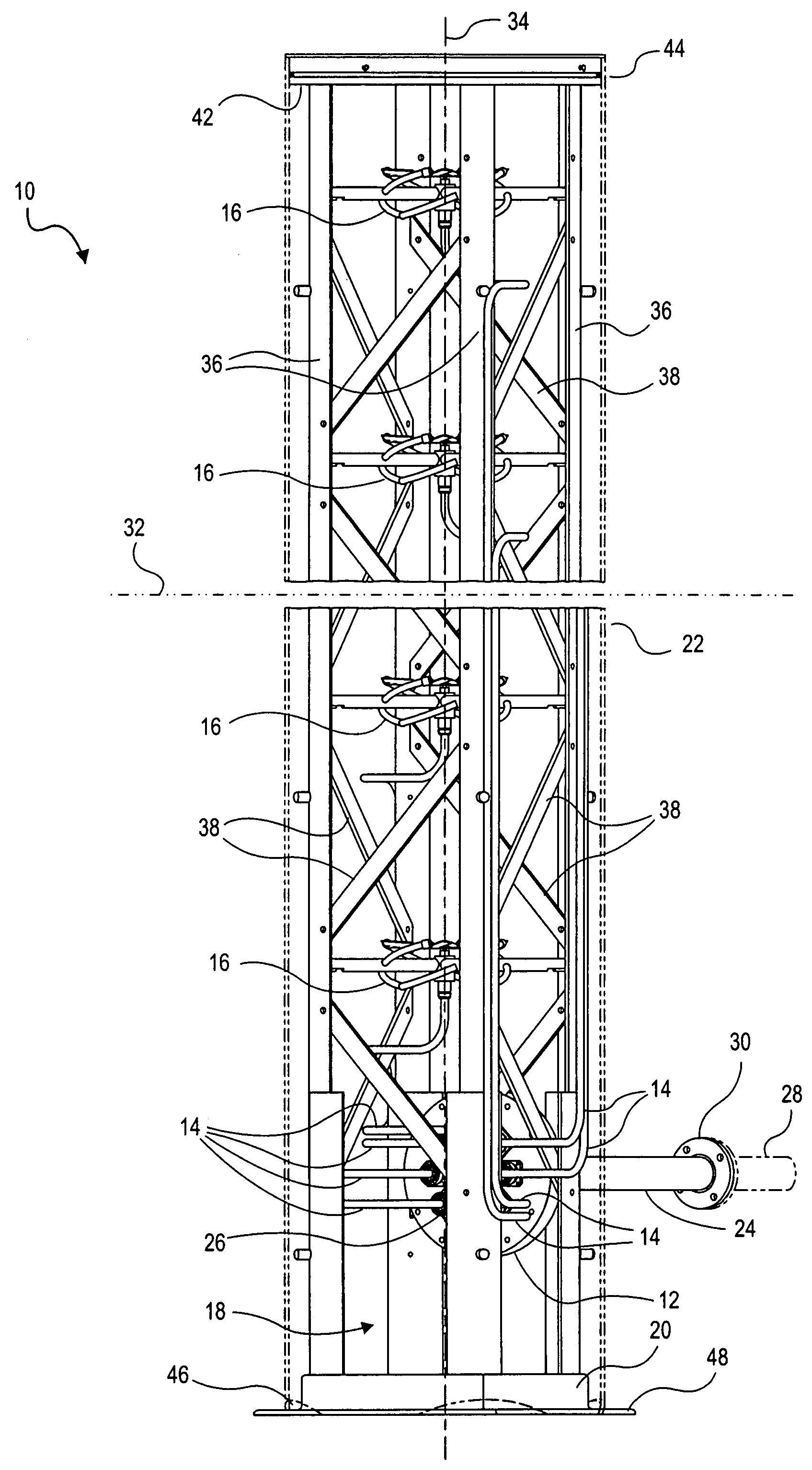
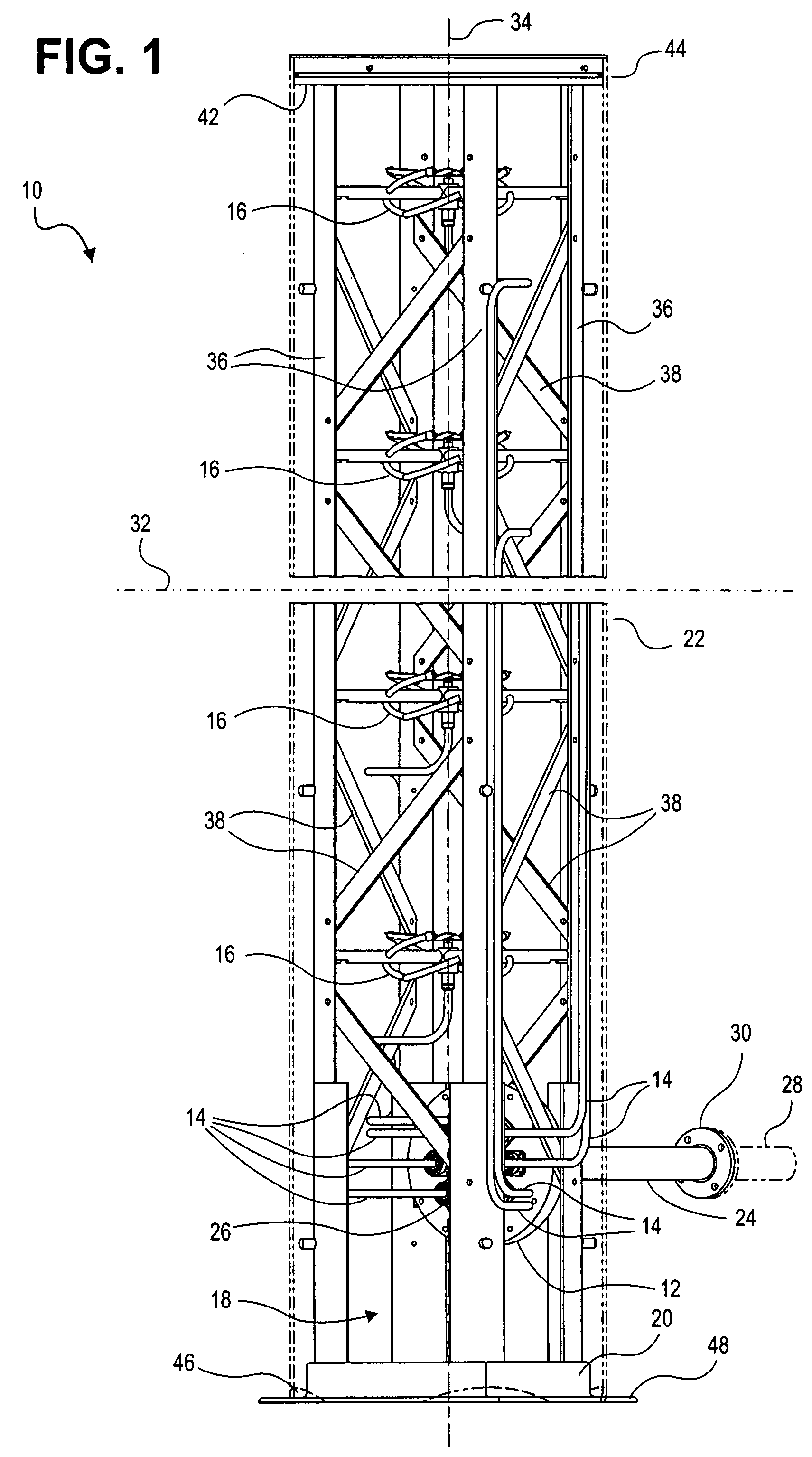
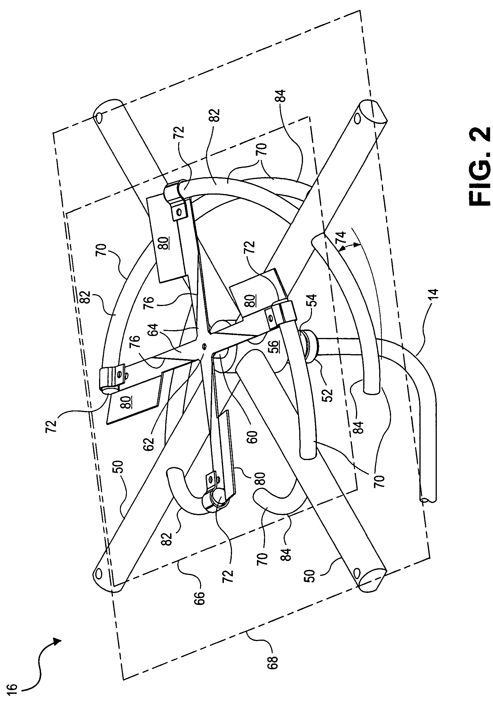
[0025]The present invention is shown in the figures, wherein like numerals refer to like elements throughout. Earlier designs for circularly polarized, high-gain, omnidirectional antennas for high L-band generally have high wind loading, weight, and complexity, and are generally not designed for ordinary broadcast applications. The present invention overcomes these disadvantages at least in part, having instead the characteristics described below.

[0026]Regarding bandwidth issues, S-band development provides an instructive archetype for antennas according to the present invention. S-band begins at 1.5 GHz, immediately above L-band; the present invention addresses primarily the latter band, previously unavailable for this type of use. Typical S-band antennas have very narrow bandwidth. The present invention provides antennas with an impedance and pattern bandwidth capable of covering the entire lower 700 MHz band (698 to 746 MHz, former television channels 52 through 59, near the uppe...


PUM


Abstract

A circularly polarized, omnidirectional, corporate-feed pylon antenna uses multiple helically-oriented dipoles in each bay, and includes a vertical and diagonal support arrangement of simple structural shapes configured to provide a frame strong enough to sustain mechanical top loads applied externally. The radiators in each bay fit within the vertical supports. The radiators are integrally formed with cross-braces, and are fed with manifold feed straps incorporating tuning paddles. A single cylindrical radome surrounds the radiative parts and the vertical supports. The antenna admits of application to the upper L-band at the full FCC-allowed ERP. Beam tilt, null fill, and vertical null can be readily accommodated.

Description

CLAIM OF PRIORITY[0001]This application claims priority to U.S. Provisional Patent Application titled, “Circularly Polarized Omnidirectional Low Wind Load Antenna Apparatus and Method”, filed Aug. 9, 2006, having Ser. No. 60 / 836,397, which is hereby incorporated by reference in its entirety.FIELD OF THE INVENTION[0002]The present invention relates generally to radiating systems. More particularly, the present invention relates to single-feed circularly polarized omnidirectional broadcast antennas.BACKGROUND OF THE INVENTION[0003]The auction of the 700 MHz spectrum by the Federal Communications Commission (FCC) resulted in part from the shift of television broadcasting from analog to digital service. Some of the new license holders have begun rollout of a Digital Video Broadcast to Handheld (DVB-H) mobile television (TV) entertainment service. Since receivers for this service may be expected to be integrated into cell phones and similar devices, circularly polarized broadcast signals...

Claims


Application Information

Patent Timeline
Patent Type & Authority Patents(United States)
IPC IPC(8): H01Q1/12
CPCH01Q1/005H01Q1/246H01Q1/427H01Q21/24H01Q21/26
Inventor SCHADLER, JOHN L.
Owner SPX CORP
Why Eureka
Try Eureka