Lens driving apparatus

a technology of driving apparatus and lens, which is applied in the direction of printers, cameras, instruments, etc., can solve the problems of difficult miniaturization of the lens driving apparatus, and achieve the effects of reducing the number of yokes, reducing the outer dimension, and enhancing the magnetic flux density of the magn

Active Publication Date: 2010-01-19
NEW SHICOH MOTOR CO LTD
View PDF3 Cites 78 Cited by
  • Summary
  • Abstract
  • Description
  • Claims
  • Application Information

AI Technical Summary

Benefits of technology

[0006]In view of the aforementioned circumstances, it is an object of the present invention is to provide a lens driving apparatus that reduces a base in an outer size to make it possible to miniaturize the apparatus.
[0008]According to the present invention, each magnet is provided at the position corresponding to each corner portion of the base between the outer peripheral wall and the inner peripheral wall. A space between the outer peripheral wall and the inner peripheral wall, which are positioned at the base side portion, is made narrower than a space between the outer peripheral wall and the inner peripheral wall, which are positioned at the base corner portion. As a result, when the yoke is attached to the base in such a manner that the outer peripheral wall is placed at substantially the same position as the side portion (one side of the square) of the base, the outer dimension of the base, as viewed from the plane, can be reduced by the thickness of the magnet.
[0010]Since the position of the flat wall portion of the yoke substantially coincides with the position of the side portion of the base, a dead space at each corner portion of the base can be made smaller than the case in which the entirety of the outer periphery wall of the yoke is annularly formed. Furthermore, the magnet is provided on the inner peripheral side of the arc wall portion of the outer peripheral wall and no magnet is provided on the inner peripheral side of the flat wall portion. In this condition, for example, when peripheral equipment is provided to be adjacent to the lens driving apparatus, it is possible to increase a distance between the magnet provided on the inner peripheral side of the arc wall portion and the peripheral equipment, thereby making it possible to reduce the influence of the magnetic field of the magnet on the peripheral equipment.
[0012]Since the magnet, which is substantially triangularly shaped as viewed from the plane, is fitted into the corner portion of the outer peripheral wall, a distance between a vertex of the triangle and a side being opposed to the vertex can be increased to make it possible to enhance the magnetic flux density of the magnet while reducing the outer dimension. Moreover, since the magnet, which is substantially triangularly shaped as viewed from the plane, is fitted into the corner portion of the outer peripheral wall, the magnet can be positioned by only fitting the magnet into the corner portion of the outer peripheral wall and the fixture of the magnet can be attained with a simple adhesion.
[0014]Since the engage projection portion that positions the base is formed on the outer peripheral wall of the yoke, the yoke can be easily positioned in attaching the yoke to the base, and this facilitates the manufacture.
[0016]According to the present invention, since the magnet, which is substantially triangularly shaped as viewed from the plane, is fitted into the corner portion of the outer peripheral wall, a distance between the vertex of the triangle and the side being opposed to the vertex can be increased to make it possible to enhance the magnetic flux density of the magnet while reducing the outer dimension. Moreover, since each magnet may not be placed at the base side portion, a space between the outer peripheral wall and the edge of the opening portion, which are positioned at the base side portion, can be made narrower than a space between the outer peripheral wall and the inner side wall, which are positioned at the base corner portion. As a result, the outer dimension of the base can be reduced to make it possible to miniaturize the lens driving apparatus. Furthermore, the arc-shape inner side wall is formed on only the edge of the opening portion where the magnet opposes. On the edge of the opening portion where the outer peripheral wall, on which no magnet is provided, opposes, no inner side wall is formed. As a result, the amount of yokes can be reduced by the portion where no inner side wall is provided, thereby making it possible to achieve light weight and cost reduction.

Problems solved by technology

As a result, there was a problem in which the outer dimension of the base was increased to cause difficulty in miniaturizing the lens driving apparatus.

Method used


Image

  • Lens driving apparatus
  • Lens driving apparatus
  • Lens driving apparatus

Examples


first embodiment

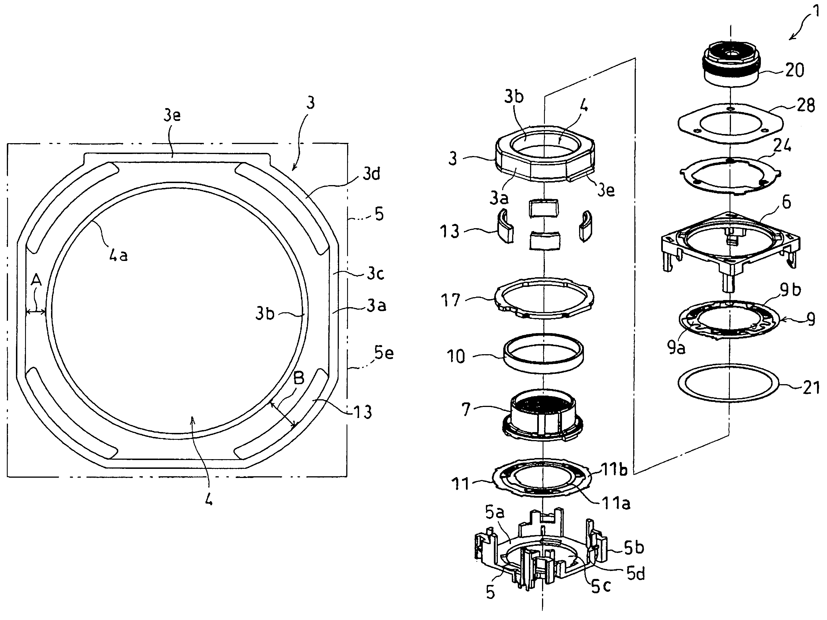
[0029]A lens driving apparatus 1 is one that is incorporated into an autofocus lens for a cellular phone and includes a substantially U-shape (in cross-section) yoke 3, a base 5 to which the yoke 3 is attached, a frame 6 that supports the base 5, a cylindrical carrier 7 provided on an inner peripheral side of the yoke 3, a coil 10 provided on an outer peripheral side of the carrier 7, a front spring 9 provided at a front position in a direction of an optical axis of the carrier 7, and a back spring 11 provided at a back position in a direction of the optical axis of the carrier 7.

[0030]The base 5 is substantially square-shaped as viewed from the plane, and has a substantially flat base portion 5a and base-side connecting portions 5b formed at four corners of the base portion 5 in a standing condition. The base portion 5a has a circular opening hole 5c and engaging portion 5d that is engaged with engage projection portion 3e formed on the outer peripheral wall 3a of the yoke 3. The ...

second embodiment

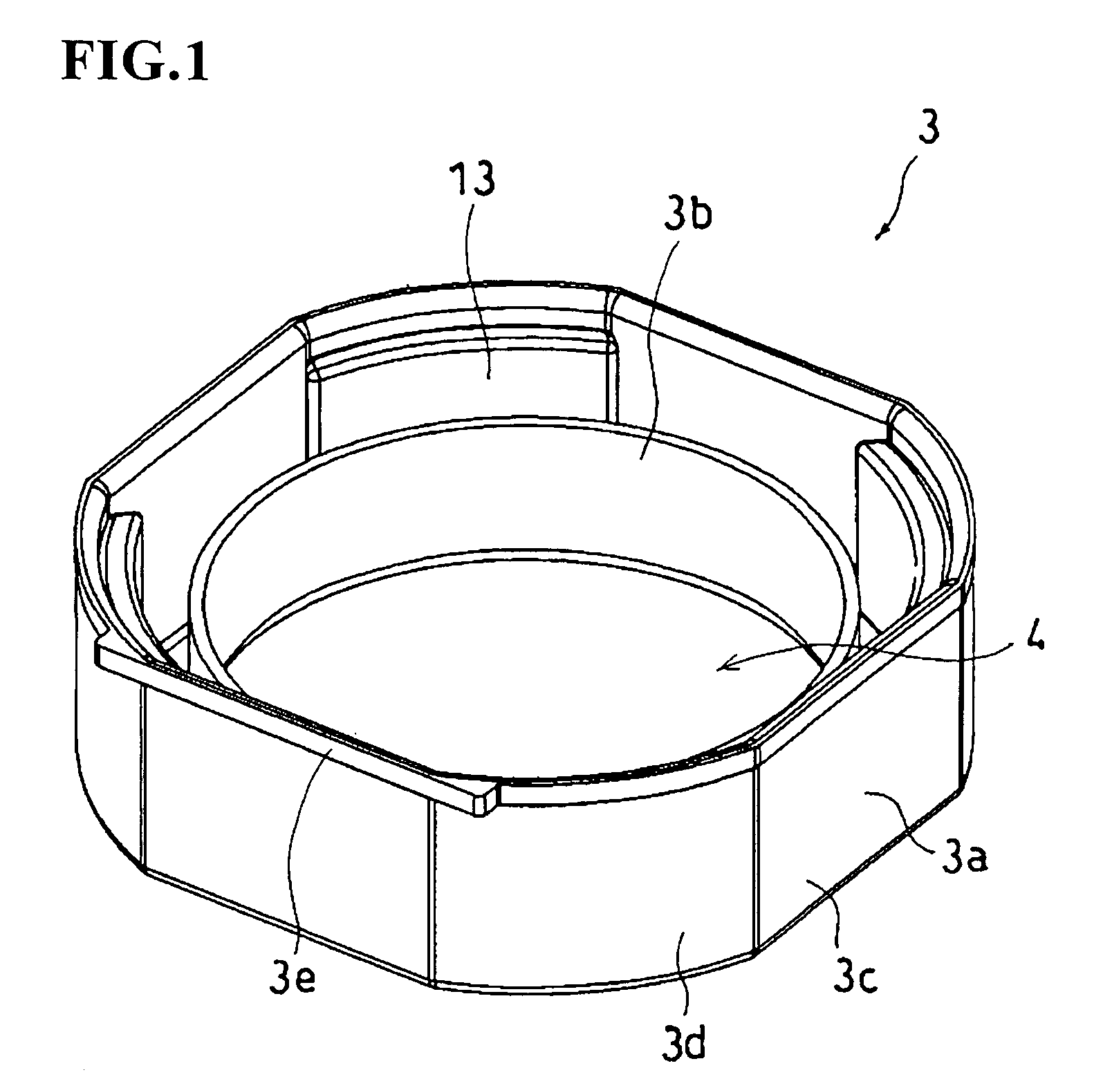
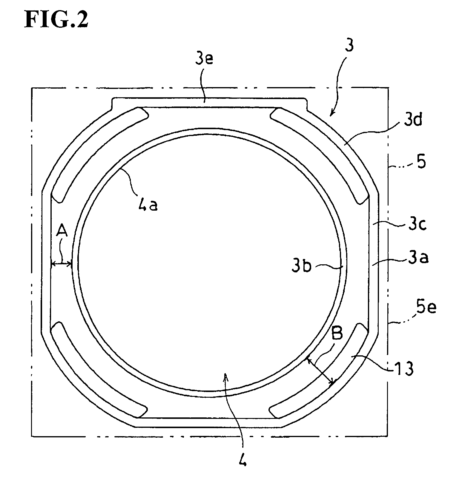
[0042]FIG. 6 is a perspective view illustrating a yoke extracted from a lens driving apparatus ; and FIG. 7 is a plane view of the yoke illustrated in FIG. 6.

[0043]As illustrated in FIGS. 6 and 7, the outer peripheral wall 3a of the yoke 3 is substantially square-shaped as viewed from the plane, and the magnet 13, which is substantially triangularly shaped as viewed from the plane, is provided on each corner portion of the outer peripheral wall 3a. An inner peripheral surface 13a of each magnet 13 is substantially arc-shaped, and the spaces between the inner peripheral walls 3b and the inner peripheral surfaces 13a of the respective magnets 13 are equally formed.

[0044]In this embodiment, each magnet 13, which is substantially triangularly shaped as viewed from the plane, is fitted into the corner portion of the outer peripheral wall 3a of the yoke 3. Accordingly, in attaching the magnets 13 to the yoke 3, the magnets 13 can be positioned by only fitting the magnets 13 into the corne...

third embodiment

[0047]In the third embodiment, each magnet 13, which is substantially triangularly shaped as viewed from the plane, is fitted into the corner portion of the outer peripheral wall 3a, and an inner side wall 3g, which is arc-shaped as viewed from the plane, is provided on an edge 4a of the opening portion 4 where each magnet 13 opposes. Moreover, in connection with each magnet 13, one side 13c of the triangle abutting to the outer peripheral wall 3a is longer than the other side 13d and end portions 13e of adjacent two magnets 13 are abutted to each other.

[0048]Since each magnet 13 may not be placed at the base side portion, a space (D shown in FIG. 9) between the outer peripheral wall 3a and the edge 4a of the opening portion 4, which are positioned at the base side portion, can be made narrower than a space (C shown in FIG. 9) between the outer peripheral wall 3a and the inner side wall 3g, which are positioned at the base corner portion. As a result, the outer dimension of the base...


PUM

PropertyMeasurementUnit
electromagnetic forceaaaaaaaaaa
thicknessaaaaaaaaaa
outer sizeaaaaaaaaaa

Abstract

A lens driving apparatus 1 of the present invention includes a substantially cylindrical yoke 3; a base 5 to which the yoke 3 is attached; a carrier 7 having a lens; a coil 10; and a magnet 13, wherein the carrier 7 is moved in a direction of an optical axis of a lens by electromagnetic force generated by passing current through the coil 10, the base 5 is substantially square-shaped as viewed from a plane, the yoke 3 is placed at an inner position of the base 5, the yoke 3 has an outer peripheral wall 3a and an annular inner peripheral wall 3b to be spaced to each other, each magnet is placed between the outer peripheral wall and the inner peripheral wall and at a position corresponding to a base corner portion of the base 5, and a space between the outer peripheral wall 3a and the inner peripheral wall 3b positioned at a base side portion 3e is made narrower than a space between the outer peripheral wall 3a and the inner peripheral wall 3b positioned at the base corner portion.

Description

BACKGROUND OF THE INVENTION[0001]1. Field of the Invention[0002]The present invention relates to a lens driving apparatus.[0003]2. Description of the Related Art[0004]Unexamined Japanese Patent Publication No. 2004-280031 discloses a lens driving apparatus including a substantially cylindrical yoke, a base to which the yoke is attached, a carrier that holds a lens, a coil, and a magnet, wherein current is made to flow to the coil, and thereby the carrier is moved in a direction of an optical axis of the lens. In the above lens driving apparatus, there is disclosed a structure in which the yoke is provided to have a space between an inner peripheral wall and an outer peripheral wall and the ring-shape magnet is provided therebetween in a circumferential direction.[0005]However, in the aforementioned prior art, since the ring-shape magnet is provided between the inner peripheral wall and the outer peripheral wall, the space between the inner peripheral wall and the outer peripheral ha...

Claims


Application Information

Patent Timeline
Patent Type & Authority Patents(United States)
IPC IPC(8): G02B7/02G03B13/00G03B13/34G11B7/00
CPCH02K41/0356G02B7/08
Inventor SHIRAKI, MANABUSEKIGUCHI, NAOKI
Owner NEW SHICOH MOTOR CO LTD
Why Eureka
Try Eureka