Flow sensor and method for measuring the volume and/or flow speed of a medium

a flow sensor and flow rate technology, applied in the field of flow rate sensors, can solve the problems of inability to arrange radially outside the gear wheel, i.e. frontally relative to the tooth, and is not feasible on spatial grounds alone, so as to improve the measurement accuracy and reduce the equipment outlay

Inactive Publication Date: 2010-01-26
VSE VOLUMENTECHNIK GMBH
View PDF11 Cites 6 Cited by
  • Summary
  • Abstract
  • Description
  • Claims
  • Application Information

AI Technical Summary

Benefits of technology

[0014]The object of the present invention is to propose a practicable solution for a flow ...

Problems solved by technology

An arrangement radially outside of the gear wheel, i.e. frontally relative to a tooth, is not fe...

Method used


Image

  • Flow sensor and method for measuring the volume and/or flow speed of a medium
  • Flow sensor and method for measuring the volume and/or flow speed of a medium
  • Flow sensor and method for measuring the volume and/or flow speed of a medium

Examples


Embodiment Construction

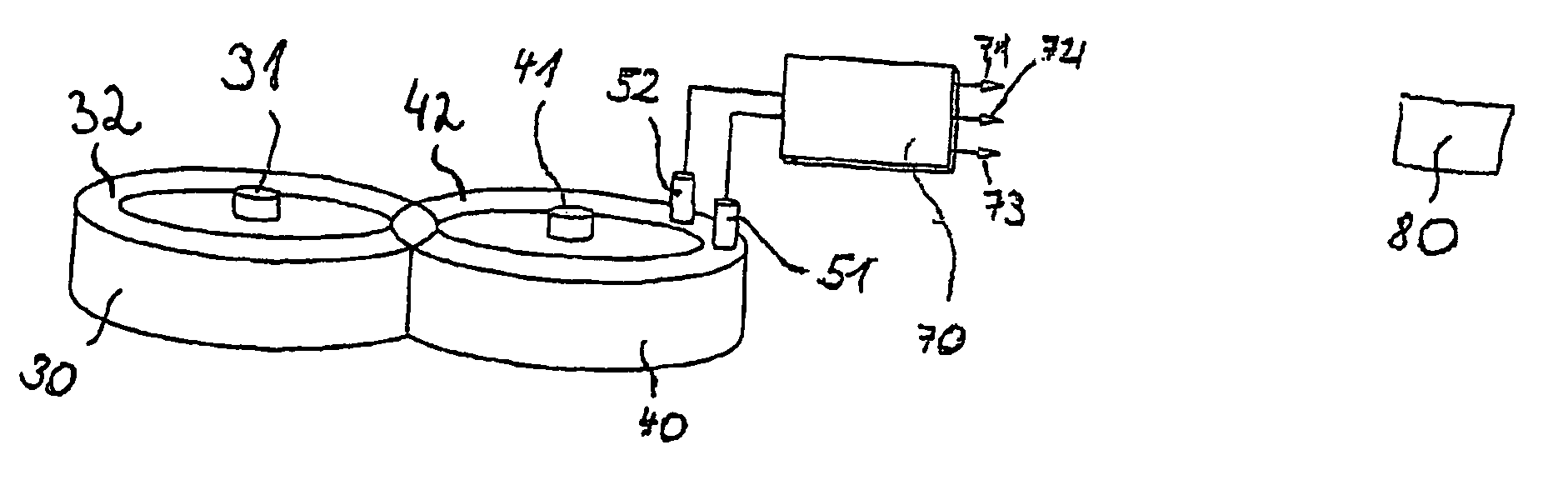
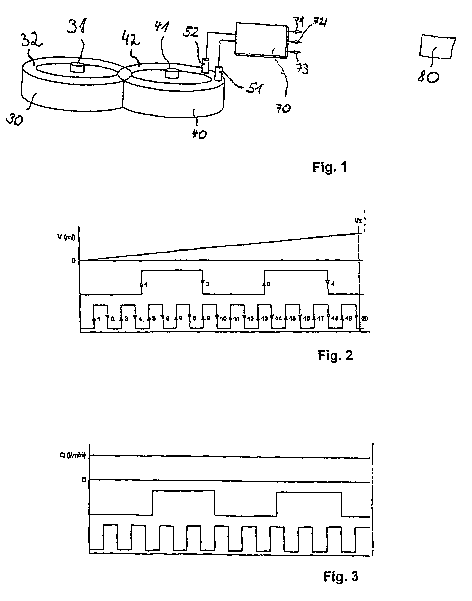
[0045]In FIG. 1 the basic principle of the evaluation of the data of a flow rate sensor is illustrated. In a housing a measuring chamber is situated (neither of which are shown). In this measuring chamber a first measuring mechanism element 30, in particular a first gear wheel is to be seen on the left of the diagram. This first measuring mechanism element 30 or first gear wheel is freely rotatable about a vertical axis 31 and at the outside has teeth 32, which are reproduced here in the diagram only as a whole by their envelope curve.

[0046]This first measuring mechanism element 30 meshes with a second measuring mechanism element 40 of a substantially identical construction, i.e. in particular a second gear wheel. This is freely rotatable about an axis 41 disposed parallel to the axis 31. The second gear wheel or second measuring mechanism element 40 has teeth 42, of which here too only an envelope curve is illustrated.

[0047]The teeth 32 and 42 of the two measuring mechanism element...


PUM


Abstract

A flow sensor comprises a measuring chamber, into which a medium may be introduced and then removed, the volume and/or flow speed of which is to be measured. Freely rotating measuring elements are mounted in the measuring chamber Furthermore, at least one sensor for the measurement of magnetic fields and/or changes in magnetic fields is provided and a circuit to which the output signals from the sensor(s) are supplied. The sensor(s) provide an output signal and supply the same to the circuit. The output signal varies periodically on each passage of a single tooth and a corresponding tooth gap on one of the measuring elements, between a minimum and a maximum value. Depending on the position of the tooth relative to the sensor(s) the output signal takes on a reproducible intermediate value. The circuit is embodied such as to convert the intermediate values into discrete values, representative of part volumes of the volumes pumped between two teeth.

Description

TECHNICAL FIELD[0001]The invention relates to a flow rate sensor having a measuring chamber, into which a fluid, the volume and / or flow rate of which is to be measured, can be fed and then discharged, having measuring mechanism elements disposed in the measuring chamber and mounted in a freely rotatable manner, having at least one sensor for measuring magnetic fields and / or variations of magnetic fields, and having a circuit device, to which the output signals of the sensor or sensors are supplied.[0002]The invention further relates to a method of measuring the volume and / or the rate of flow of a medium by means of a flow rate sensor, which comprises a measuring chamber having measuring mechanism elements disposed therein and mounted in a freely rotatable manner and having at least one sensor for measuring magnetic fields and / or variations of magnetic fields.BACKGROUND OF THE INVENTION[0003]Flow rate sensors are also known as volume sensors. Generally, they take the form of displace...

Claims


Application Information

Patent Timeline
IPC IPC(8): G01F15/00G01F3/06G01F3/10
CPCG01F3/06G01F3/10
Inventor ERTLER, WERNER
Owner VSE VOLUMENTECHNIK GMBH
Why Eureka
Try Eureka