Spark ignition and fuel injector system for an internal combustion engine

a fuel injection system and spark ignition technology, applied in the field of internal combustion engines, can solve the problems of limited mounting of conventional spark plugs on the side of cylinders, achieve the effects of improving ignition and combustion, increasing spacing and non-grounded relationship, and increasing voltage potential

Inactive Publication Date: 2010-01-26
ADVANCED PROPULSION TECH
View PDF15 Cites 47 Cited by
  • Summary
  • Abstract
  • Description
  • Claims
  • Application Information

AI Technical Summary

Benefits of technology

[0007]The present invention utilizes a pair of fuel injector tube and spark electrode combinations that separately extend through opposing sides of a cylinder. Each injector tube delivers atomized air / fuel mixture adjacent to a spark gap defined between the electrodes and each electrode is integral with the fuel injector tubes. The invention provides three key improvements over prior art ignition systems utilized in internal combustion engines: 1) a larger spark is capable of being produced; 2) the spark is capable of being produced in the diametrical center of the cylinder; and 3) more complete burn is achieved. All these improvements are significant in helping to improve the efficiencies of the engine. Since the electrodes are integral with the fuel injectors, there is a cooling effect produced by the fuel passing through the body of the electrodes. This helps to prevent excessive heat buildup in the electrodes and resultant premature ignition.
[0009]In the disclosed embodiment, each electrode is connected to the opposite end of an ignition coil to take advantage of the full voltage potential created by the coil. Preferably, neither electrode is grounded. As such, this allows for a spark gap that can be approximately twice what it could be when compared to a conventional spark plug which has a grounded electrode. A larger spark makes it possible to improve ignition and resulting combustion within the cylinder.
[0011]The present invention provides several key improvements to the ignition system of an internal combustion engine. A larger spark is produced because of the increased spacing and non-grounded relationship of the opposing electrodes, as well as the higher voltage potential available to be applied between the electrodes. The spark gap is located more central to the combustion chamber formed in the cylinder to improve ignition and combustion. Heat produced by combustion within the cylinder causes the fuel within the fuel delivery tubes to be vaporized and emitted as a fog or cloud of atomized fuel vapor. The fuel vapor is injected adjacent to the spark gap to improve combustion efficiency. The heat absorbed by the fuel passing through the fuel delivery tubes causes the electrodes to be cooled sufficiently to prevent heat buildup in the electrodes which may otherwise cause premature auto ignition.

Problems solved by technology

In such an engine that has no cylinder head, the mounting of a conventional spark plug is limited to the side of a cylinder.

Method used


Image

  • Spark ignition and fuel injector system for an internal combustion engine
  • Spark ignition and fuel injector system for an internal combustion engine
  • Spark ignition and fuel injector system for an internal combustion engine

Examples


Embodiment Construction

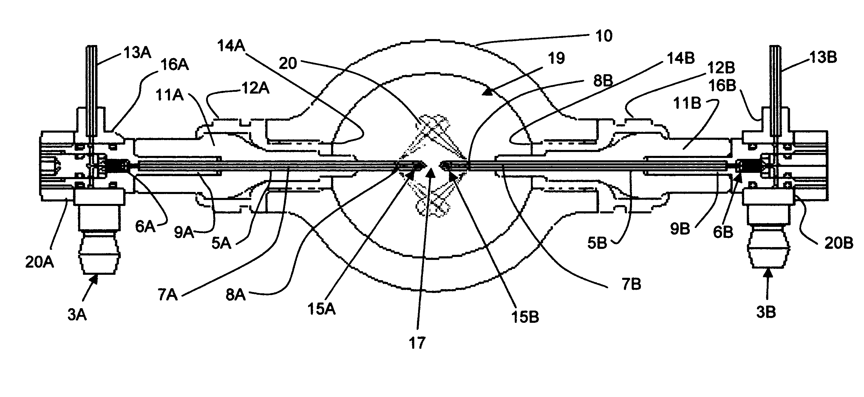
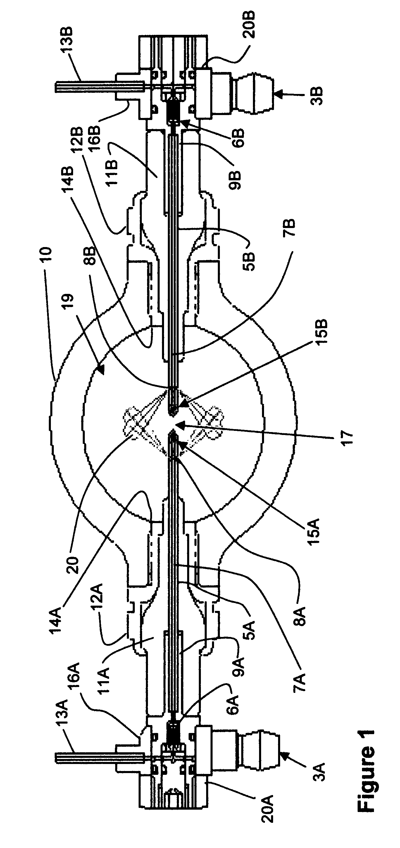
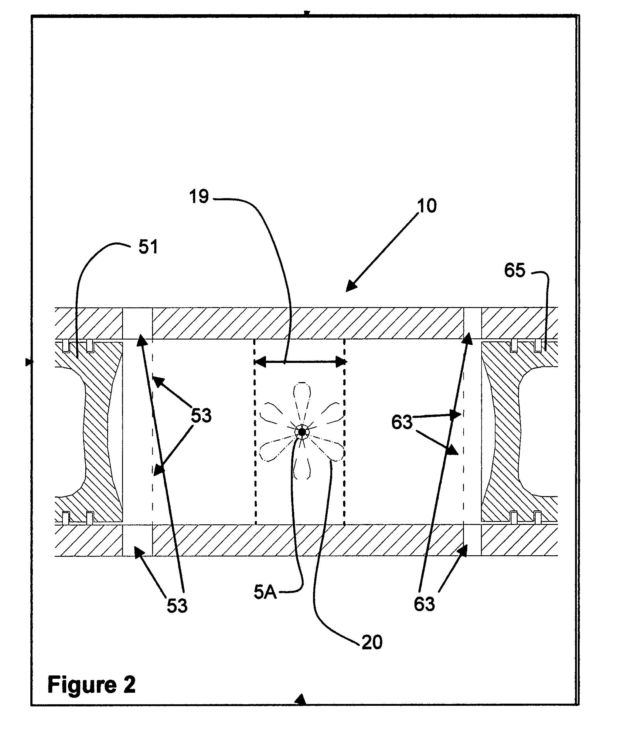
[0016]In FIG. 1, an embodiment of the present invention is shown mounted in a cylinder 10 of an internal combustion engine. In a cross-section of the combustion chamber portion 19 of the cylinder 10, opposing electrode tips 15A and 15B are shown mounted on each side to extend towards each other. The electrodes 15A and 15B are separated from each other by a predetermined distance that defines an air / spark gap 17. Each electrode is correspondingly integrated with fuel tubes 5A and 5B, respectively. The fuel tubes are electrically conductive and contain capillary passages 7A and 7B which allow fuel to flow therein. Injector nozzle ports 8A and 8B are formed in the fuel tubes to allow atomized fuel vapor to be injected into the combustion chamber adjacent to gap 17.

[0017]Electrode tip 15A is mounted at the end of an electrically conductive fuel tube 5A that extends from a tube casing 11A. Tube casing 11A is formed of a non-conducting insulator material, such as a high temperature cerami...


PUM


Abstract

An improved spark ignition system for an internal combustion engine that includes a pair of electrodes disposed to extend from opposite sides and into a combustion chamber to form a spark gap between them that is central to the combustion chamber. Each electrode is integral with a conductive fuel delivery tube that contains a capillary passage and fuel outlet ports adjacent the electrode. The heat from combustion conducted into the electrodes and fuel delivery tubes is used to vaporize the fuel within the capillary passages before it exits the outlet ports as an atomized fog into the combustion chamber adjacent the spark gap. The vaporization of the fuel flowing in the capillary passages absorbs energy from the electrodes and thus performs a cooling effect on the electrodes. The spacing of the electrodes from opposite sides of the cylinder also allows a design that can utilize and increased spark gap to produce a larger spark across the gap.

Description

RELATED APPLICATION[0001]This application claims benefit of U.S. provisional application Ser. No. 60 / 818,628 filed Jul. 5, 2006.TECHNICAL FIELD[0002]This invention is related to the field of internal combustion engines and more specifically to a spark ignition and fuel injection system utilized therein.BACKGROUND[0003]Conventional internal combustion engines are configured with spark plugs which contain two electrodes. A powered electrode is mounted within an insulator sleeve to have one end located within the cylinder. A ground electrode is configured to be opposed across an air gap with respect to the powered electrode. Such spark plugs are unitary in nature, since they contain both electrodes in a single unit.[0004]In some cases, spark plugs have been combined with fuel injectors to inject fuel through a nozzle into air gap portion of the spark plug. Such combinations also are unitary in nature since they contain the spark plug elements and fuel injector elements in a single unit...

Claims


Application Information

Patent Timeline
Patent Type & Authority Patents(United States)
IPC IPC(8): F02M57/06F02P13/00
CPCF02M57/06
Inventor HOFBAUER, PETEREBBESON, BENGT
Owner ADVANCED PROPULSION TECH
Why Eureka
Try Eureka