
Ballast circuit for electrostatic particle collection systems

a particle collection and electrostatic technology, applied in the field of electrostatic particle collection systems, can solve the problems of non-uniform plasma that would defeat the primary benefits of a multiple electrode corona discharge system, power through a single electrode is limited, and breakdown and resistance values are not usually in high demand for most electrical applications

Inactive Publication Date: 2010-01-26
SARNOFF CORP
View PDF27 Cites 4 Cited by
  • Summary
  • Abstract
  • Description
  • Claims
  • Application Information

AI Technical Summary

Benefits of technology

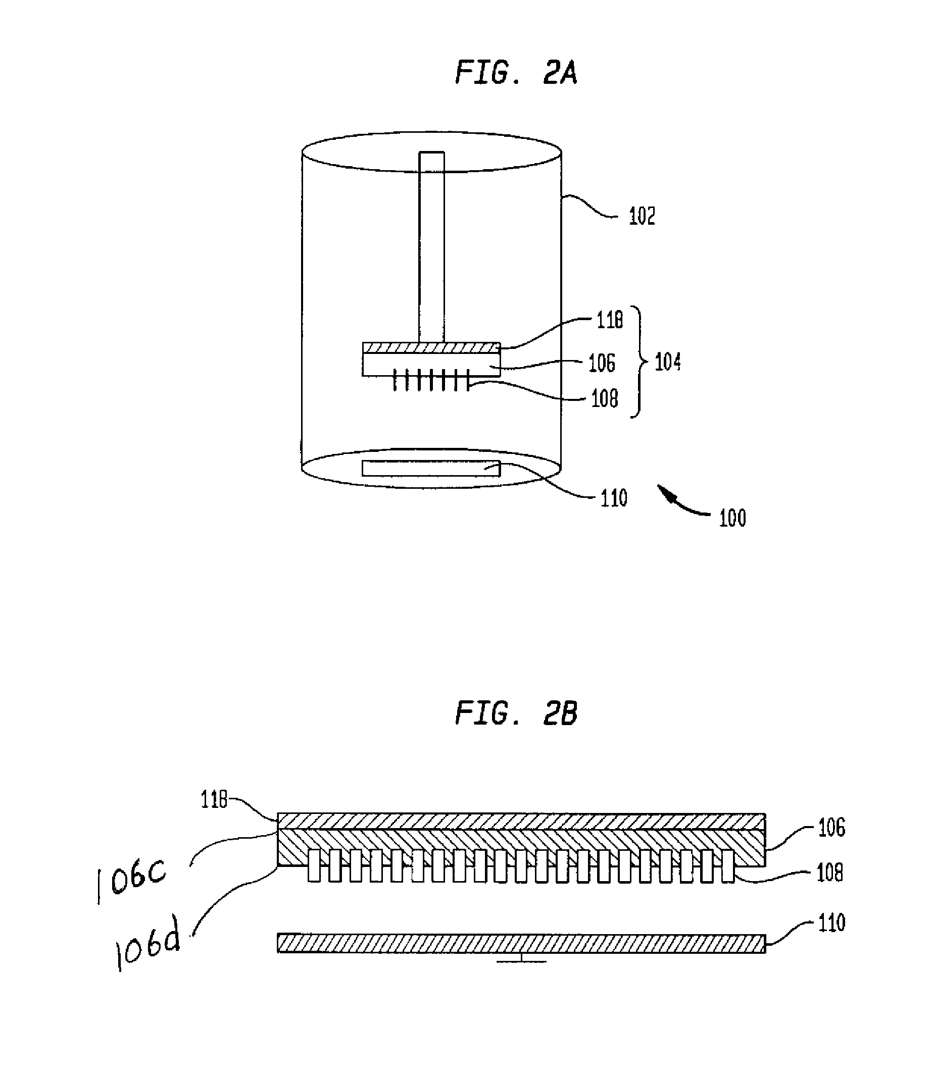
"The present invention provides a ballast circuit for an electrostatic particle collection system and the method for fabricating the same. The circuit comprises a conductive plastic material having a first end and a second end, such that the first end is connected to a power source. The circuit also comprises at least one corona electrode protruding from the second end of the conductive plastic material. The distance between the inner surface of the conductive plastic material and the corona electrode varies electrical resistance and determines the voltage breakdown of the circuit. The technical effect of the invention is to provide a reliable and efficient ballast circuit for an electrostatic particle collection system."

Problems solved by technology

The resulting non-uniform plasma would defeat the primary benefits of a multiple electrode corona discharge system; that is, uniformity of electric field and charge density in the particle collection zone.
Power through a single electrode is limited by lowering the electrode voltage as more current passes through the ballast resistor to the electrode.
However, the breakdown and resistance values are not usually in high demand for most electrical applications.
As a result, these resistors are typically much more expensive than lower voltage, lower value resistors.

Method used


Image

  • Ballast circuit for electrostatic particle collection systems
  • Ballast circuit for electrostatic particle collection systems
  • Ballast circuit for electrostatic particle collection systems

Examples


Embodiment Construction

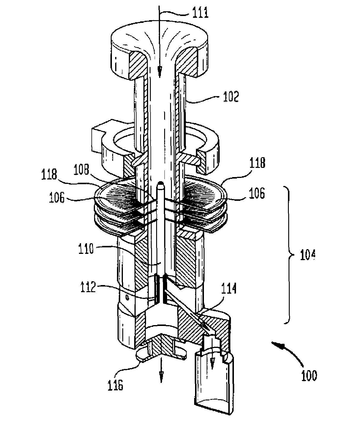
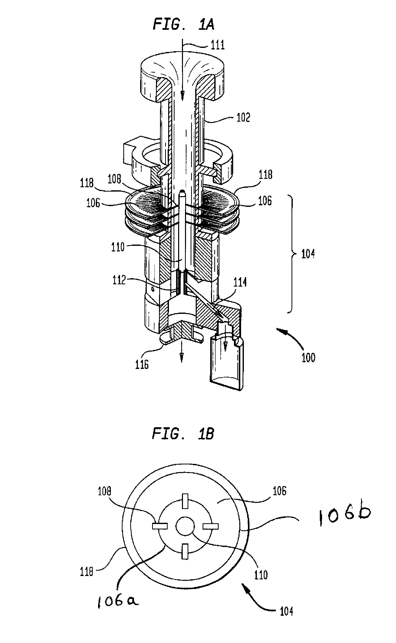
[0017]As will be described in greater detail below, a conductive plastic material has been shown to meet the requirements for the resistive ballasting of multi-electrode corona discharge arrays. Typical ballast resistor electrical requirements are resistance greater than or equal to 10.sup9 ohm and voltage breakdown of greater than or equal to 10 kV across the terminals. Conductive plastics possess a unique combination of material properties that enable its use for this application. Use of this material will substantially reduce the cost to manufacture multi-electrode corona discharge arrays where a large number (i.e. >10 electrodes) of discharge elements is required.

[0018]Furthermore, using a conductive plastic as the resistive element of a multi-electrode ballast circuit enables a large number of circuit designs and geometries that can be used to accommodate the variations of particle collection geometry. A brief description of the multi-electrode ballast circuit for cylindrical a...


PUM

PropertyMeasurementUnit
distanceaaaaaaaaaa
distanceaaaaaaaaaa
voltage breakdownaaaaaaaaaa

Abstract

The present invention provides a ballast circuit and method for fabricating the same for multi-electrode corona discharge arrays. The circuit includes a conductive plastic material and at least one corona electrode protruding from the conductive plastic material. The distance between the plastic material and the corona electrode varies and controls the electrical resistance and determines the voltage breakdown of the circuit. Additionally, a particle collection surface may preferably be located within the conductive plastic material or preferably be separated from the material depending on the circuit design and configuration.

Description

CROSS-REFERENCE TO RELATED APPLICATIONS[0001]This application claims the benefit of U.S. Provisional Patent Application No. 60 / 722,078 filed Sep. 29, 2005, the entire disclosure of which is incorporated herein by reference.FIELD OF THE INVENTION[0002]The invention relates generally to electrostatic particle collection systems, and more specifically to methods for fabricating ballast circuits for multi-electrode corona discharge arrays in electrostatic particulate collection systems.BACKGROUND OF THE INVENTION[0003]Highly efficient, low power particle collection devices have been demonstrated using multiple electrode corona discharge arrays. The advantages of multiple electrode corona discharge arrays for particle collection are described in “System and Method for Spatially Selective Particulate Deposition And Enhanced Particulate Deposition Efficiency”, filed Apr. 18, 2006, having an application Ser. No. 11 / 405,787, issued as U.S. Pat. No. 7,261,764, and in “Corona Charging Device a...

Claims


Application Information

Patent Timeline
Patent Type & Authority Patents(United States)
IPC IPC(8): B03C3/60
CPCB03C3/41B03C3/68B03C3/86B03C2201/10
Inventor PLETCHER, TIMOTHY ALLENWARSHAWSKY, STEVEN
Owner SARNOFF CORP
Learn More