Method and device for dynamically measuring the unbalance of a rotor

a technology of dynamic measurement and unbalance, which is applied in the direction of measurement devices, structural/machine measurement, instruments, etc., can solve the problems of sensitivity and accuracy of measurement, housing portions attached to the turbocharger centre housing substantially detract from vibration characteristics and therefore from the measurement of unbalance, etc., to achieve less stiffness, less bending portion, and less bending portion stiffness

Active Publication Date: 2010-02-02
SCHENCK ROTEC GMBH
View PDF24 Cites 20 Cited by
  • Summary
  • Abstract
  • Description
  • Claims
  • Application Information

AI Technical Summary

Benefits of technology

[0011]It has proven beneficial if the resiliently yielding elements are fastened with the radially internal sector portion on the housing and the radially external sector portion on the bearing ring, so that they do not project in the radial direction beyond the bearing ring. The spring elements which interconnect the two sector portions can be bent in an S- or Z-shape. This has the advantage that little radial space is required to achieve the necessary soft spring. The two sector portions and the spring elements interconnecting them can be manufactured integrally in a simple manner in one piece, for example from a spring sheet steel. This allows cost-effective manufacture.
[0012]Another advantageous embodiment of a device according to the invention provides for the housing to have two spring rods to which the bearing housing or the bearing ring can be fastened, the spring rods being arranged in a common plane parallel to the rotational axis of the rotor and extending in the direction of the rotational axis of the rotor. In this embodiment the bearing housing can be moved in all radial directions relative to the housing and can be rotated around a radial axis in the plane. The spring rods are preferably arranged in a vertical plane and each have at least one bending portion of lesser stiffness at the same region. The stiffness of the bending portion can be less in the horizontal direction than in the vertical direction. In particular, the stiffness of the spring rods in the horizontal direction can be approx. 10% of the stiffness of the spring rods in the vertical direction. The greater stiffness of the spring rods in the vertical direction serves to support the weight of rotor and bearing housing.

Problems solved by technology

This method has the disadvantage that the relatively large mass comprising the bearing housing and turbine housing compared with the mass of the rotor greatly reduces the vibrations induced by the unbalance of the rotor and therefore the sensitivity and accuracy of the measurement.
Here too, the housing portions attached to the turbocharger centre housing substantially detract from the vibration characteristics and therefore from the measurement of the unbalance.

Method used


Image

  • Method and device for dynamically measuring the unbalance of a rotor
  • Method and device for dynamically measuring the unbalance of a rotor
  • Method and device for dynamically measuring the unbalance of a rotor

Examples


Embodiment Construction

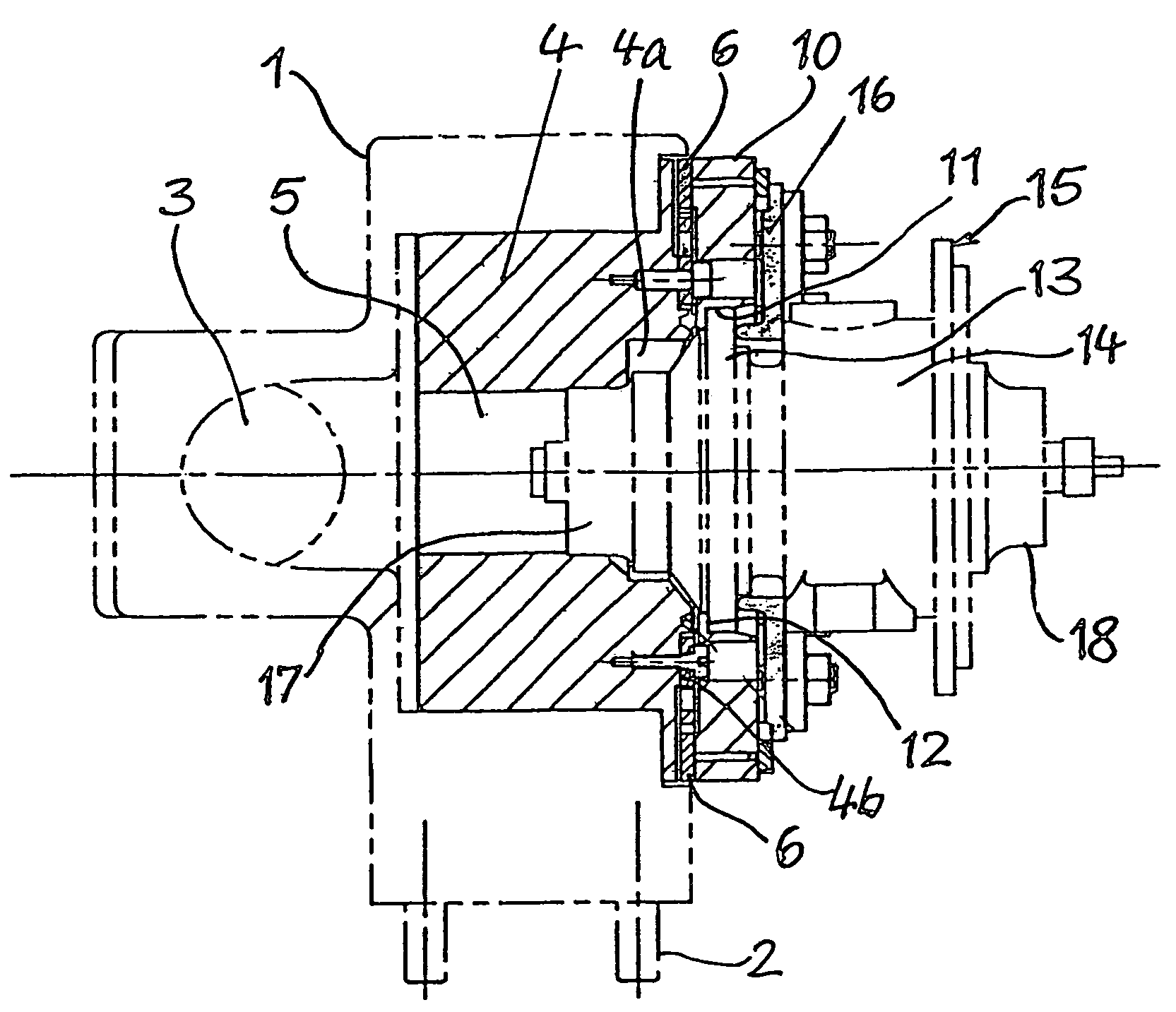
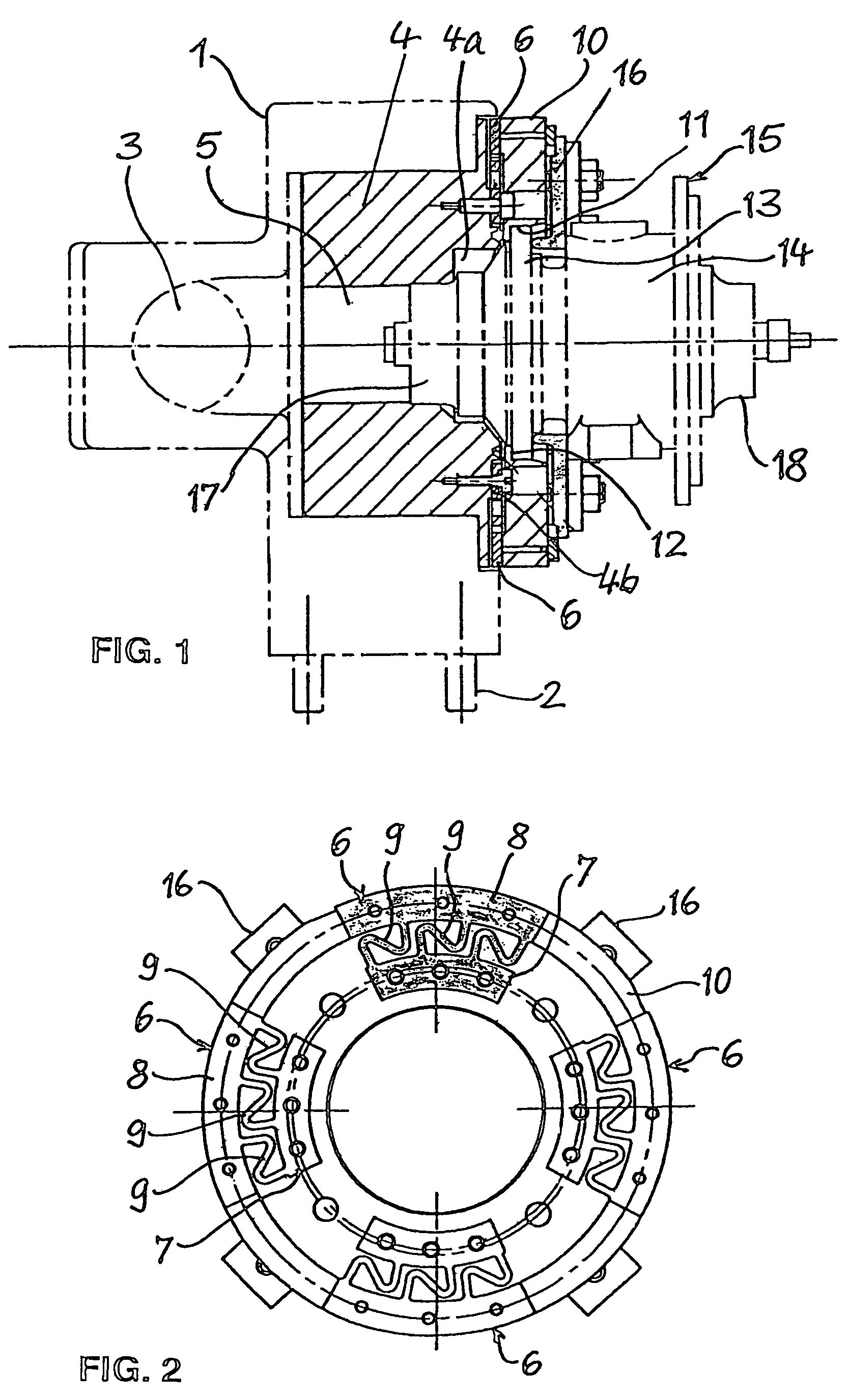
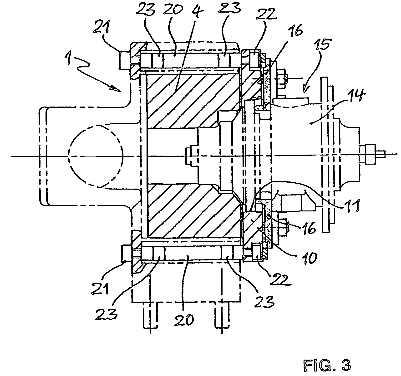
[0017]The unbalance measuring device shown in FIG. 1 comprises a housing 1 which can be fastened on a pedestal or frame by means of bolts 2. The housing 1 contains a flow channel 3 and an annular spiral housing 4 whose central aperture 5 is connected to the flow channel 3. The spiral housing 4 has on the end face facing away from the flow channel 3 a spiral channel 4a and a ring face 4b concentric to its longitudinal central axis on which four resiliently yielding elements 6 of the same design are fastened by means of bolts each at the same distance from the longitudinal central axis and at the same distance from one another.

[0018]As can be seen from FIG. 2, the resiliently yielding elements 6 substantially have the shape of ring sector-shaped plates which are divided by recesses into a radially internal sector portion 7, a radially external sector portion 8 and Z-shaped spring elements 9 interconnecting the two sector portions. The elements 6 consist respectively of one piece and c...


PUM


Abstract

Dynamically measuring the unbalance of a rotor arranged in a device housing (1) and rotating at high angular velocity, wherein the rotor is supported in a separate bearing housing (14), involves the following steps: fastening the bearing housing (14) on the device housing (1) with interposition of resiliently yielding elements (6) so that the bearing housing (14) can be moved relative to the device housing (1) in at least two spatial dimensions and the rotor is arranged in a working position in the device housing (1) suitable for driving, accelerating the rotor, measuring the vibrations induced by unbalance while the rotor rotates at a substantially normal working speed, determining the phase position of the induced vibrations to the relative position of the rotor at the measuring speeds, and using the measured vibrations and the phase position to determine the unbalance of the rotor to be compensated.

Description

FIELD OF THE INVENTION[0001]The invention relates to a method for dynamically measuring the unbalance of a rotor arranged in a housing and rotatable at high angular velocity, said rotor being mounted in a separate bearing housing, and to a device suitable for carrying out the method. In particular the invention relates to a method and a device for measuring the unbalance of the rotor of an exhaust gas-driven turbocharger.BACKGROUND INFORMATION[0002]Exhaust gas-driven turbochargers have a rotor which rotates in operation at a very high speed of frequently over 100,000 revolutions per minute and therefore has to be very accurately balanced for the avoidance of noises and excessive bearing loads. As a rule the rotor consists of a shaft supported in an associated bearing housing, said shaft carrying at one end a turbine wheel and at the other end a compressor wheel. For reasons of accuracy the unbalance of the rotor is measured at an angular velocity corresponding substantially to norma...

Claims


Application Information

Patent Timeline
Patent Type & Authority Patents(United States)
IPC IPC(8): G01M1/00
CPCF01D5/027G01M1/04F05D2220/40
Inventor THELEN, DIETER
Owner SCHENCK ROTEC GMBH
Why Eureka
Try Eureka