Dual-chamber type oil pan and engine equipped with same

a dual-chamber, oil pan technology, applied in the direction of machines/engines, mechanical equipment, transportation and packaging, etc., can solve the problem that engine oil is not suitable for circulation, and achieve the effect of high viscosity, rapid rise, and effective prevention of sucking

Inactive Publication Date: 2010-02-02
TOYOTA JIDOSHA KK
View PDF8 Cites 22 Cited by
  • Summary
  • Abstract
  • Description
  • Claims
  • Application Information

AI Technical Summary

Benefits of technology

[0027]As described above, according to the present invention, the first chamber is allowed to have a small amount of engine oil, so that the temperature of the engine oil can be raised quickly at the time of cold start. The large-capacity portion is provided below the small-capacity portion, so that air can be effectively prevented from being sucked through the suction port even when the engine oil has a high viscosity and a difficulty in returning to the oil pan from the engine block, and a reduced amount of engine oil remains in the first chamber.

Problems solved by technology

Immediately after the engine is started in a cold state, the engine oil stored in the oil pan is cold and has a high viscosity, so that the engine oil is not in a state suitable for circulating through the individual parts of the engine and lubricating them.

Method used


Image

  • Dual-chamber type oil pan and engine equipped with same
  • Dual-chamber type oil pan and engine equipped with same
  • Dual-chamber type oil pan and engine equipped with same

Examples


first embodiment

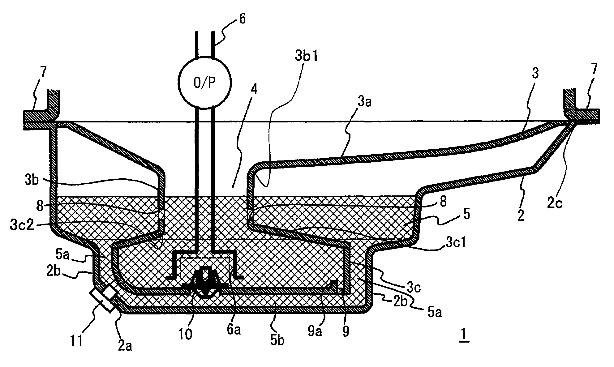
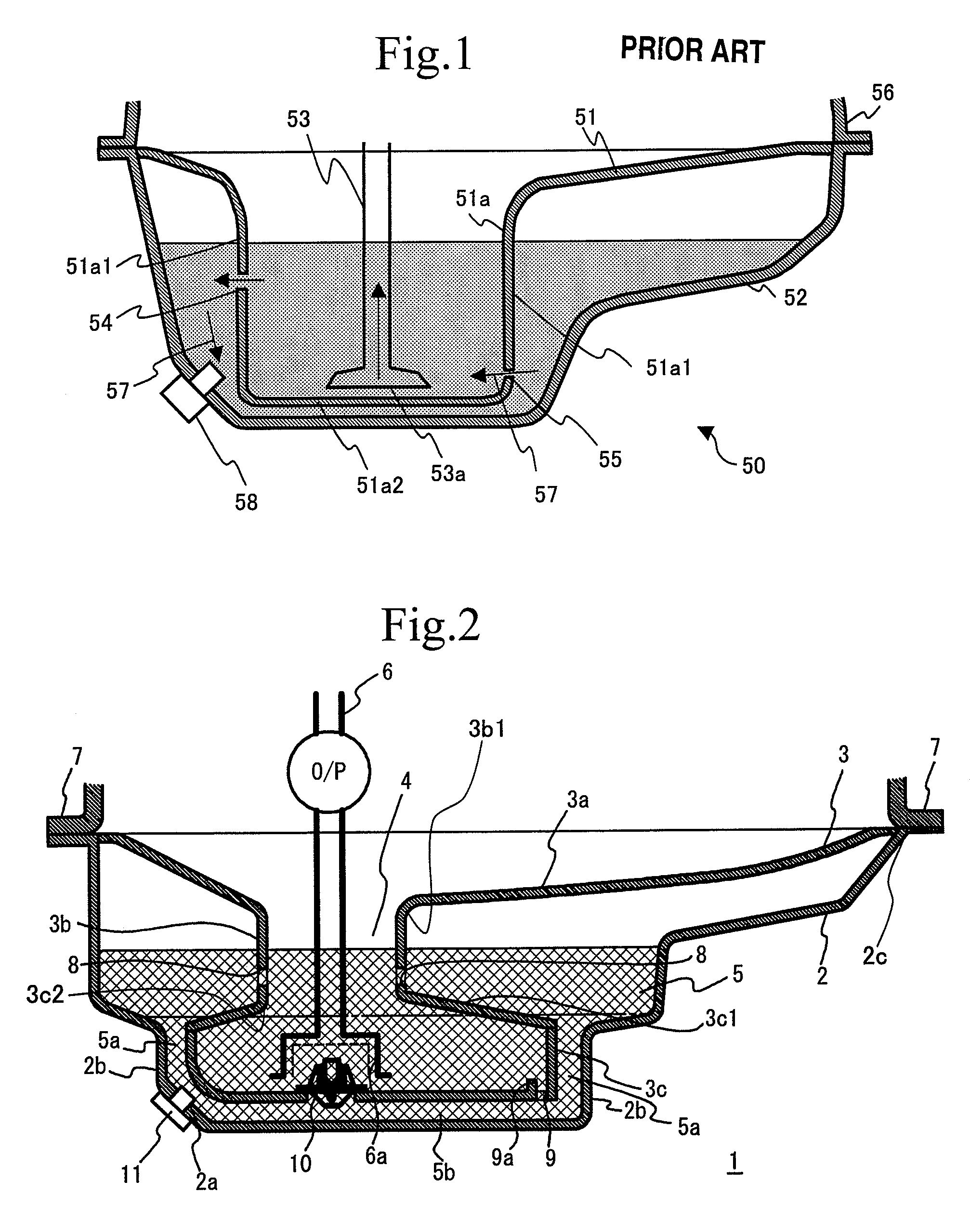
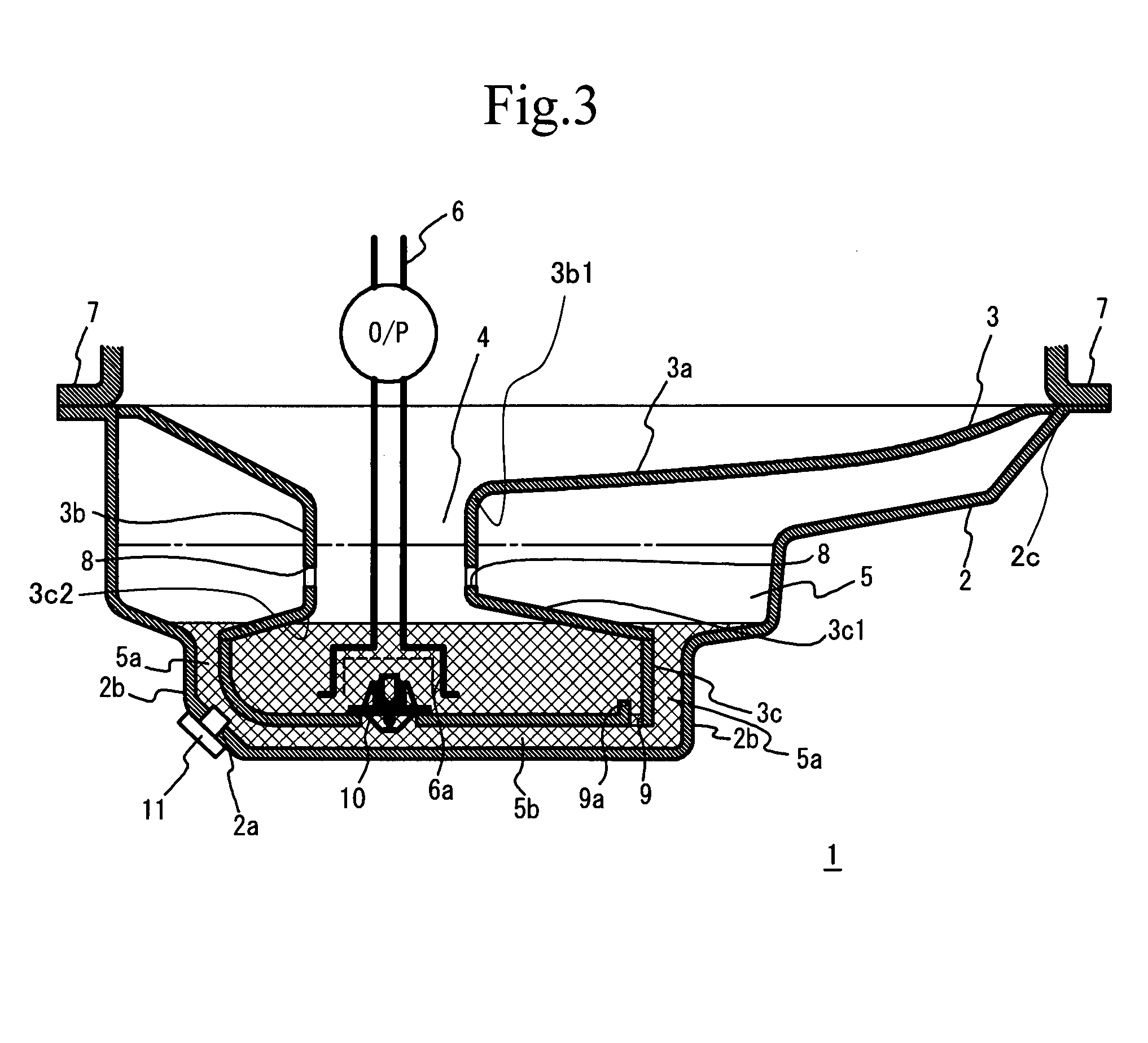
[0041]A dual-chamber oil pan in accordance with a first embodiment of the present invention will now be described. FIGS. 2 and 3 are respectively cross-sectional views of a dual-chamber oil pan 1 in according with the first embodiment of the present invention. More specifically, FIG. 2 shows a state in which engine oil stored is up to a given level prior to engine start, and FIG. 3 shows another state in which some engine oil has been supplied to an engine block 7 from the dual-chamber oil pan 1 and the remaining engine oil in the dual-chamber oil pan 1 is thus reduced. The dual-chamber oil pan 1 is attached to a lower portion of the engine block 7, and is equipped with an oil pan separator arranged within an oil pan 2. The oil pan separator 3 defines a first chamber 4 and a second chamber 5 within the oil pan 2. The first chamber 4 communicates with the inside of the engine block 7. The second chamber 5 is arranged so as to cover or surround the first chamber 4, and is located arou...

second embodiment

[0053]A description will now be given, with reference to FIGS. 5 through 7, of a second embodiment of the present invention. A dual-chamber oil pan 20 in accordance with the second embodiment differs from the dual-chamber oil pan 1 of the first embodiment as follows. An oil pan separator 23 provided in an oil pan 22 of the dual-chamber oil pan 20 has a narrowed portion 23d in addition to an oil receiving portion 23a, a small-capacity portion 23b and a large-capacity portion 23c as those of the oil pan separator 3 of the dual-chamber oil pan 1. The suction port 6a is disposed within the narrowed portion 23d. Further, an eaves-like plate 24 is provided above the suction portion 6a.

[0054]In the dual-chamber oil pan 20 thus structured, the suction port 6a may be placed more deeply than that in the dual-chamber oil pan 1 of the first embodiment by a depth equal to the length of the narrowed portion 23d. This structure secures an increased distance between the oil level and the suction p...

third embodiment

[0058]A description will now be given, with reference to FIGS. 8 through 10, of a third embodiment of the present invention. FIG. 8 is a plan view of a dual-chamber oil pan 30 in accordance with the third embodiment, and FIG. 9 is a cross-sectional view taken along a line A-A shown in FIG. 8. FIG. 10 is a cross-sectional view taken along a line B-B shown in FIG. 8. Referring to these figures, a dual-chamber oil pan 30 has an oil pan separator 33 provided in an oil pan 32. The oil pan separator 33 divides the inner area of the oil pan 32 into the first chamber 4 communicating with the engine block 7 and the second chamber 5 arranged so as to cover the first chamber 4. This structure of the oil pan separator 33 is the same as that of the dual-chamber oil pan 1 of the first embodiment.

[0059]The first chamber 4 includes a large-capacity portion 33c provided on the bottom side of the oil pan separator 33, and a small-capacity portion 33b that is connected to the large-capacity portion 33...


PUM


Abstract

A dual-chamber oil pan includes an oil pan provided below an engine block, an oil pan separator that is provided within the oil pan and defines a first chamber communicating with the engine block, and a second chamber provided around the first chamber, and a suction port disposed within the first chamber. The first chamber includes a large-capacity portion including a bottom portion of the oil pan separator, and a small-capacity portion located above and integrally formed with the large-capacity portion.

Description

TECHNICAL FIELD[0001]The present invention relates to an oil pan that is disclosed under an engine block and stores engine oil.BACKGROUND ART[0002]Conventionally, engine oil is used to lubricate and cool the engine. The engine oil is stored in an oil pan disposed under the engine and is circulated through individual parts of the engine by an oil pump. The engine oil circulated through the individual parts drops into the oil pan located below these parts. The engine oil dropped into the oil pan is recirculated through the individual parts by the oil pump. During the circulation, the engine oil receives heat from the individual parts of the engine and cools them. The engine oil also acts to form oil films in the individual parts of the engine, thereby promoting lubrications among the parts, preventing the parts from oxidizing, and so forth.[0003]Immediately after the engine is started in a cold state, the engine oil stored in the oil pan is cold and has a high viscosity, so that the e...

Claims


Application Information

Patent Timeline
Patent Type & Authority Patents(United States)
IPC IPC(8): F02B77/00
CPCF01M5/001F01M11/0004F01M2011/0045F01M5/02F01M11/00
Inventor KOBAYASHI, HIDEOARISAWA, KATUHIKOYAMASHITA, YOSHIOHAYASHI, KUNIHIKOMIZUTA, TAMETOSHI
Owner TOYOTA JIDOSHA KK
Why Eureka
Try Eureka