Pressure sintering furnace

Inactive Publication Date: 2010-07-28
ZHUZHOU CEMENTED CARBIDE EQUIP
View PDF0 Cites 21 Cited by
  • Summary
  • Abstract
  • Description
  • Claims
  • Application Information

AI Technical Summary

Problems solved by technology

[0003] 1. Since the insulation door and the graphite door inside the pressure furnace need to be opened and closed frequently, some furnace types realize the elastic pressing of the graphite door, but cannot make it open and close independently, and some furnace types realize the independent opening and closing of the graphite, but unable to make it elastic
In short, the independent elastic pressing of the graphite door has not been realized in the prior art, and it is difficult to ensure the sealing of the inner cavity of the graphite cylinder, and there is a phenomenon that the wax vapor escapes to the outer cavity of the furnace.
[0004] 2. The sealing ring of the pressure furnace door is easily damaged by overheating
The furnace door sealing ring is a vulnerable part. If the seal is not tight during the use of the equipment, it will easily lead to leakage and affect product quality.
[0005] 3. The dewaxing valve is blocked by the condensation of wax vapor, which blocks the switching action of the valve. It often occurs that the switching action is difficult, and the closing is not tight and the gas leaks.
[0006] 4. Because the hydrogen pumping step is often required during the working process of the pressure furnace, and the pressure furnace mechanical pump in the prior art generally does not adopt hydrogen explosion-proof measures, there are potential safety hazards
In the prior art, the heating element is generally divided into three bands to form a circle. The diameter of the graphite heating rod used is less than 15mm, and the length is more than 1100mm, resulting in poor mechanical properties of the heating rod, easy to break during installation and use, and frequent maintenance.
[0008] 6. Due to the particularity of the pressure furnace, the electrode current is generally quite large. If the furnace shell electrodes use high magnetic permeability materials, the high temperature generated by eddy currents may affect the safety of the furnace shell.
[0009] 7. The pressurization system has not effectively controlled the flow of hydrogen, nitrogen and other gases according to the requirements of the production process, so as to ensure the gas pressure required by the product during dewaxing and sintering, and to ensure the effective bonding of alloy powder and particles during the production process , improve product density
[0010] Since the pressure sintering furnaces in the prior art still have the above-mentioned structural defects, it is inevitable that the blank will be oxidized and absorb moisture due to direct contact with the air, which is not conducive to the control of the carbon content in the alloy, resulting in a product qualification rate that can only reach about 80%

Method used


Image

  • Pressure sintering furnace
  • Pressure sintering furnace
  • Pressure sintering furnace

Examples


Embodiment 1

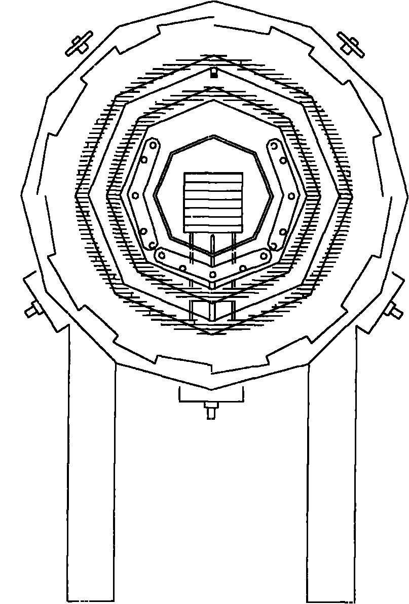
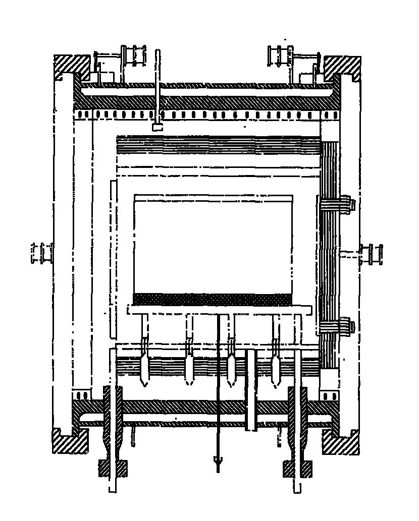
[0042] A pressure sintering furnace, such as figure 1 , figure 2 As shown, it includes a furnace shell, a vacuum system, a gas distribution system, a heating and heat preservation device, a pressurization system, a cooling system, and a pressure relief device. The furnace body is its core component, mainly including heat exchanger 1, safety plug 2, air inlet 3, insulation layer 4, furnace door 5, charging track 6, exhaust port 7, thermocouple 8, furnace shell 9, inlet Parts such as the electric column 10 and the heating element 11 are connected with the external pipe network through the interface on the furnace body. The distribution of the external pipe network system can be adjusted according to the user's installation site conditions.

[0043]The furnace shell 9 is a horizontal cylinder provided with a double-walled water jacket. The furnace door 5 on the furnace shell 9 is a quick-opening hydraulic side-rotating structure. The furnace door 5 of the furnace shell 9 inclu...

Embodiment 2

[0048] A pressure sintering furnace, such as figure 1 , figure 2 As shown, it includes a furnace shell, a vacuum system, a gas distribution system, a heating and heat preservation device, a pressurization system, a cooling system, and a pressure relief device. The furnace body is its core component, mainly including heat exchanger 1, safety plug 2, air inlet 3, insulation layer 4, furnace door 5, charging track 6, exhaust port 7, thermocouple 8, furnace shell 9, inlet Parts such as the electric column 10 and the heating element 11 are connected with the external pipe network through the interface on the furnace body. The distribution of the external pipe network system can be adjusted according to the user's installation site conditions.

[0049] The furnace shell 9 is a horizontal cylinder provided with a double-walled water jacket. The furnace door 5 on the furnace shell 9 is a quick-opening hydraulic side-rotating structure. The furnace door 5 of the furnace shell 9 incl...


PUM

PropertyMeasurementUnit
diameteraaaaaaaaaa

Abstract

The invention relates to a pressure sintering furnace used for producing hard alloys. The pressure sintering furnace comprises a furnace shell, a vacuum system, an air distribution system, a heating and thermal-insulating device, a compression system, a cooling system and a decompression device. The pressure sintering furnace is characterized in that the furnace shell is a horizontal cylinder provided with a double-wall water jacket, the furnace door on the furnace shell has a quick-opening hydraulic side-rotating structure, the furnace door of the furnace shell comprises a thermal-insulating door on the external layer of the furnace and a graphite door on the internal side of the furnace, the opening of the furnace door is controlled by a hydraulic locking device with a door-closing air cylinder, the door-closing air cylinder is provided with an elastic coupling device, and the thermal-insulating door of the furnace door is a boss thermal-insulating door. The pressure sintering furnace has stable performance and low cost and safety production can be realized by using the pressure sintering furnace, thus the uniformity of temperature field distribution in the furnace can be effectively improved and the qualification rate of products can be more than 90%.

Description

technical field [0001] The invention relates to cemented carbide sintering equipment, in particular to a pressure sintering furnace. Background technique [0002] Cemented carbide sintering is a key process in the production of cemented carbide, which plays a decisive role in the final quality of the product. At present, there are two development directions of sintering technology in the world, one is atmosphere controlled sintering, and the other is pressure sintering. Gas pressure sintering is a new process technology for cemented carbide manufacturing. It was first used in industrial production in Kennametal, USA in the late 1980s. It is a new sintering technology that uses high-pressure gas to promote product densification when the product has been degassed, the surface pores have been closed, and the binder phase is still in the liquid phase. Since this process technology can effectively reduce or eliminate residual pores and internal defects in cemented carbide, and ...

Claims


Application Information

Patent Timeline
Patent Type & Authority Applications(China)
IPC IPC(8): F27B5/05F27B5/06F27B5/16F27B5/14F27B5/18F27D1/18
Inventor 谭华茂
Owner ZHUZHOU CEMENTED CARBIDE EQUIP
Why Eureka
Try Eureka