Hydraulic fixed fixture for ultra-thin fan metal piece machining

A technology for fixing fixtures and metal parts, applied in metal processing equipment, metal processing mechanical parts, manufacturing tools, etc., can solve the problems of inconvenient operation, high labor intensity, and excessive pressing, so as to reduce the use of labor and improve the The effect of production efficiency

Inactive Publication Date: 2019-02-26
KESEN SCI & TECH DONGTAI CO LTD
View PDF7 Cites 0 Cited by
  • Summary
  • Abstract
  • Description
  • Claims
  • Application Information

AI Technical Summary

Problems solved by technology

[0003] Traditional CNC fixtures use simple fixtures and positioning pins for positioning operations, and rely on workers to load and unload and pos

Method used


Image

  • Hydraulic fixed fixture for ultra-thin fan metal piece machining
  • Hydraulic fixed fixture for ultra-thin fan metal piece machining
  • Hydraulic fixed fixture for ultra-thin fan metal piece machining

Examples


Embodiment 1

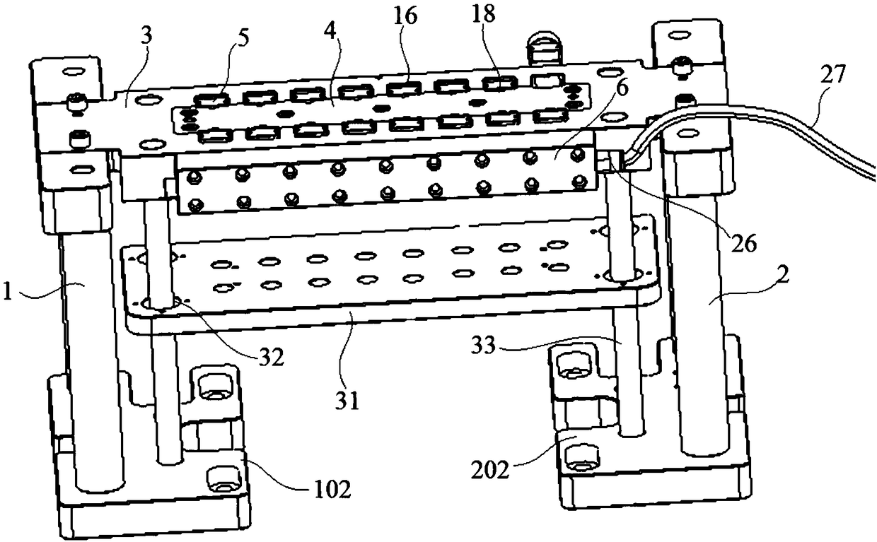
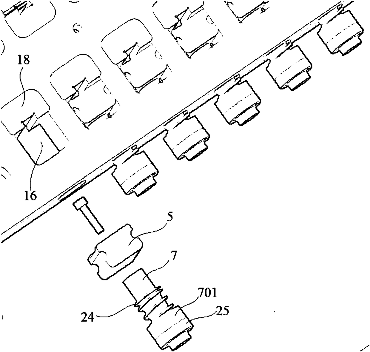
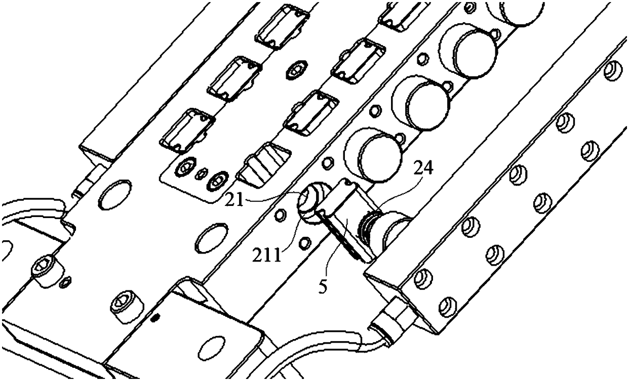
[0027]Embodiment 1: A hydraulic fixing fixture for ultra-thin fan metal parts processing, including left support 1, right support 2, fixed plate 3, positioning plate 4, chuck 5 and pressure mechanism 6, the fixed The two ends of the plate 3 are fixedly connected with the left support 1 and the right support 2 respectively, the positioning plate 4 is fixedly connected with the fixed plate 3, and the pressure mechanism 6 is symmetrically installed on both sides of the fixed plate 3 respectively. The head 5 is respectively installed on the end of the piston rod 7 of the pressure mechanism 6;

[0028] Both sides of the upper surface of the fixing plate 3 are symmetrically opened with a number of uniformly arranged relief through holes 16, and the positioning protrusions 18 and chucks 5 of the positioning plate 4 are located in the relief through holes 16, wherein the positioning protrusions 18 Located on the side close to the center, the chuck 5 is located on the side away from th...

Embodiment 2

[0033] Embodiment 2: A hydraulic fixing jig for processing ultra-thin fan metal parts, including a left support 1, a right support 2, a fixed plate 3, a positioning plate 4, a chuck 5 and a pressure mechanism 6, the fixed The two ends of the plate 3 are fixedly connected with the left support 1 and the right support 2 respectively, the positioning plate 4 is fixedly connected with the fixed plate 3, and the pressure mechanism 6 is symmetrically installed on both sides of the fixed plate 3 respectively. The head 5 is respectively installed on the end of the piston rod 7 of the pressure mechanism 6;

[0034] Both sides of the upper surface of the fixing plate 3 are symmetrically opened with a number of uniformly arranged relief through holes 16, and the positioning protrusions 18 and chucks 5 of the positioning plate 4 are located in the relief through holes 16, wherein the positioning protrusions 18 Located on the side close to the center, the chuck 5 is located on the side awa...


PUM


Abstract

The invention discloses a hydraulic fixed fixture for ultra-thin fan metal piece machining. The hydraulic fixed fixture comprises a left support, a right support, a fixed plate, a positioning plate, clamping heads and pressure mechanisms; the two ends of the fixed plate are fixedly connected with the left support and the right support respectively, the positioning plate is fixedly connected with the fixed plate, each oil seal sleeves a piston rod and is located between a flange portion and a switching surface of a T-shaped blind hole, at least two mounting through holes are formed in a movableplate, each telescopic cylinder is fixedly connected with the rear end surface of a shell, a piston rod of each telescopic cylinder penetrates through a connecting hole of the shell, each end, connected with a connecting rod, of a connecting block is provided with a connecting groove, a T-shaped part of each connecting rod is embedded into the corresponding connecting groove, and the flange of each T-shaped part is clamped with a clamping part of the corresponding connecting groove. According to the fixture, by arranging a telescopic mechanism, after all ejection operations are completed, anarc-shaped clamping jaw is pulled down backwards through the telescopic cylinder, so that a movable plate falls to the bottom surface, and loading is conducted again for the next round of machining;the structure is simple, operation is conducted conveniently and automatically, manpower and time are saved, and the work efficiency is improved.

Description

technical field [0001] The invention relates to a hydraulic fixing jig used for processing ultra-thin fan metal parts, and relates to the field of high precision machining. Background technique [0002] Smartphones are the most widely used entertainment and communication devices, and their update speed is relatively fast. Therefore, smartphone manufacturers have also put forward higher requirements. Smartphone components are inseparable from machine tool equipment, and machine tool fixtures are one of the important technological equipment to ensure machine tool processing quality, improve production efficiency, and reduce labor intensity. However, there are many problems in how to stably and effectively position the workpiece during processing. . [0003] The traditional CNC fixtures mostly use simple fixtures and positioning pins for positioning operations, and are loaded and unloaded by workers for positioning. This will lead to unstable positioning of the workpiece, too ...

Claims


Application Information

Patent Timeline
IPC IPC(8): B23Q3/00
CPCB23Q3/00B23Q2703/04B23Q2703/10
Inventor 徐金根潘群
Owner KESEN SCI & TECH DONGTAI CO LTD
Why Eureka
Try Eureka