Locking differential

a technology of differential and locking, which is applied in the direction of differential gearings, belts/chains/gearrings, mechanical instruments, etc., can solve the problems of unnecessarily high internal losses, open differentials, and the degree of slippage between tyres and road surfaces, and achieve the highest possible efficiency, high cost, and high efficiency

Active Publication Date: 2010-02-02
ALFREDSON JONAS LARS
View PDF9 Cites 11 Cited by
  • Summary
  • Abstract
  • Description
  • Claims
  • Application Information

AI Technical Summary

Benefits of technology

[0024]The purpose of the present invention is to distribute the torque of the engine, on a “driving dynamics” perspective, as optimum as possible with regard to the ability of the individual tyres to transform the torque into a tractive effort as well as to the influence of said tractive effort on the “yaw attitude” of the vehicle (i.e. yaw resisting / assisting moments). A further purpose is to achieve the aforementioned without undue mechanical complexity and the accompanying high cost and lastly with the highest possible efficiency, ie without unnecessarily high internal losses and hence with the lowest possible wear and energy consumption and lastly without conflicting with ABS and ESP (Electronic Stability Program). The above mentioned purpose is achieved according to the present invention through an apparatus comprising a differential gear and a self energizing locking device arranged between two of said differential gears three shafts, characterised by the fact that the function of said locking device, through a control signal, is controllable between four distinct working modes, said working modes can be described by the fact that;said locking device is not prevented from functioning during differentiation in any of the two differentiation directions so that any differentiation will be automatically locked regardless of differentiation direction;said locking device is prevented from functioning during differentiation in the first differentiation direction so that any differentiation in said first direction will not be locked;said locking device is prevented from functioning in (in relation to said first direction) the opposite direction so that any differentiation in said opposite direction will not be locked;said locking device is prevented from functioning during differentiation in any of the two differentiation directions so that no differentiation will be locked regardless of differentiation direction.
[0025]A differential gear that reacts to the described “crossover point” in the way that it is fully open “below” it and fully locked “above” it, totally eliminates the biggest problem of the conventional differential, namely “inside wheel spin”. It also does just that without any drawbacks in the form of yaw resisting moments during cornering. Instead it gives a virtually balanced drive for as long as both drive wheels are capable of transforming their torque into a tractive effort. Only if and when the “inside” drive wheel approaches its tractive limit, the differential will lock and the greater part of the torque will be directed to where the greatest resistance is, i.e. to the heavier loaded “outside” drive wheel, which of course to some degree will lead to a yaw assisting moment, but which will also lead to the optimization of the slip rate of the inside drive wheel. Even when driving straight ahead a differential gear reacting in this way will solve the problems of the conventional differential as it instantly will lock any beginning differentiation.

Problems solved by technology

The open differential has one functional problem.
This problem occurs if one of the driving wheels does not have enough traction to handle its half of the torque.
This problem is the reason that has brought about the development of all the various differential brake systems of today.
In reality they will not be totally equalized during differentiation since the action of the differential can not be made 100% efficient.
When a twisting force is applied to the wheels there is always a degree of slip in the contact between the tyres and the road surface.
If and when the traction limit approaches, this slip rate will be considerable.
There is also always an upper limit above which an increased slip rate will result in a decreased tractive effort.
This fact often leads to a considerable yaw resisting moment (promoting under steer).
In tight corners with good traction this yaw resisting moment can get extremely high and the resulting strain of the drive shafts etc. will of course be equally high.
The reason for this stems from the lateral load transfer that always occurs during cornering and its result is inside wheel spin.
This means that some of the theoretical differentiation gets “eaten up” by the relatively higher slip rate of the inside wheel.
This tendency is what eventually leads to the shortcomings of the open differential during cornering, however the risk of inside wheel spin will not be impending until after the differentiation has changed direction (as the traction-peak of the inside wheel will not occur until after that).
Such a statement is however not always the truth, i.e. as long as the vehicle is driving straight ahead it is correct.
The disadvantage of limited slip differentials using this principle is however that although they can be “severe” to different degrees, they will always allow some amount of one wheel spin.
Another disadvantage is that the torque biasing ability isn't as “direct” as it is in the “torque sensing” variants.
The biggest disadvantage with this principle makes itself evident if one of the drive wheels has considerably less traction than the other one.
If this is the case there is a risk that not enough torque can be applied to help lower the efficiency enough to avoid unwanted differentiation (i.e. one wheel spin).

Method used


Image

  • Locking differential
  • Locking differential
  • Locking differential

Examples


Embodiment Construction

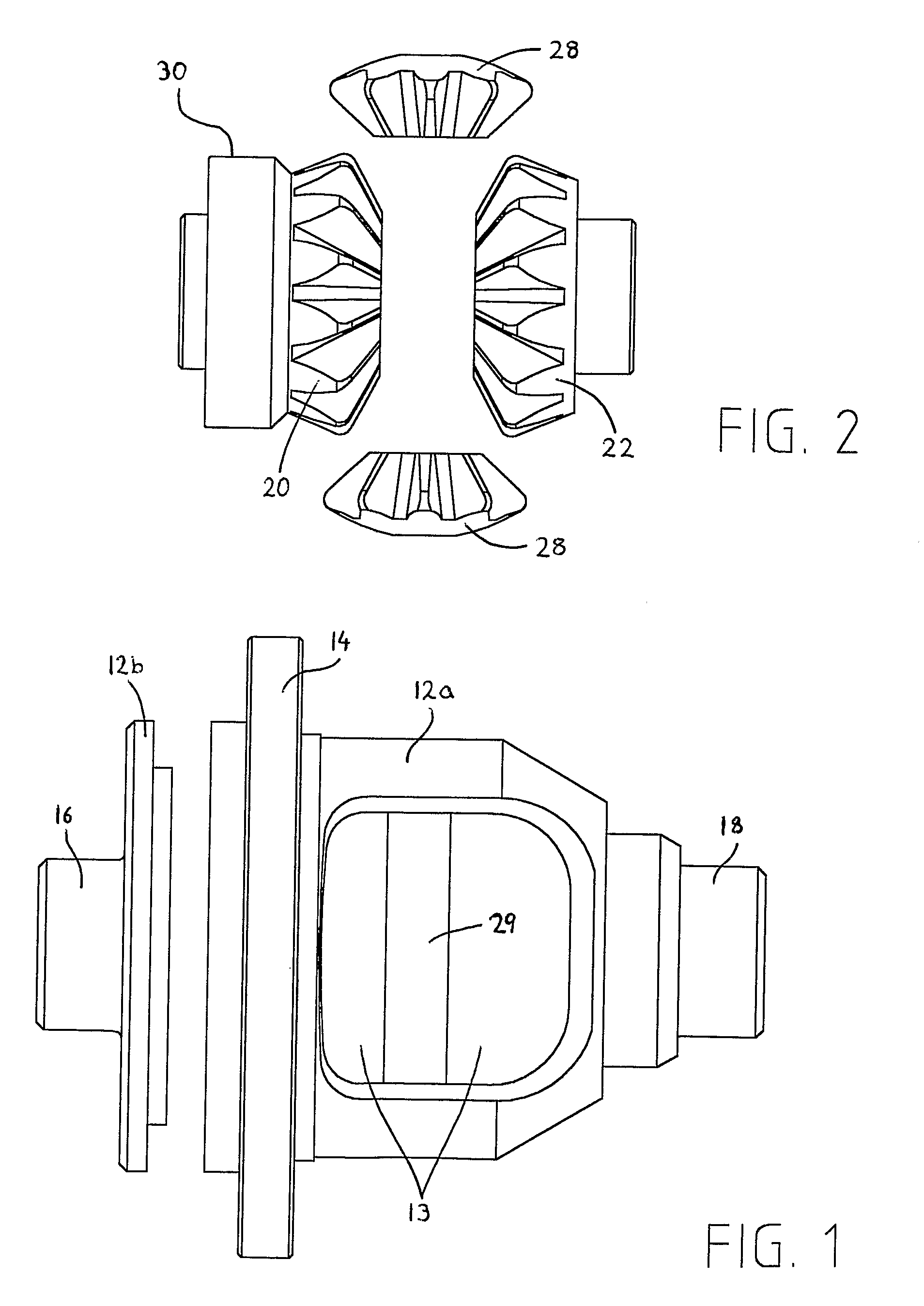
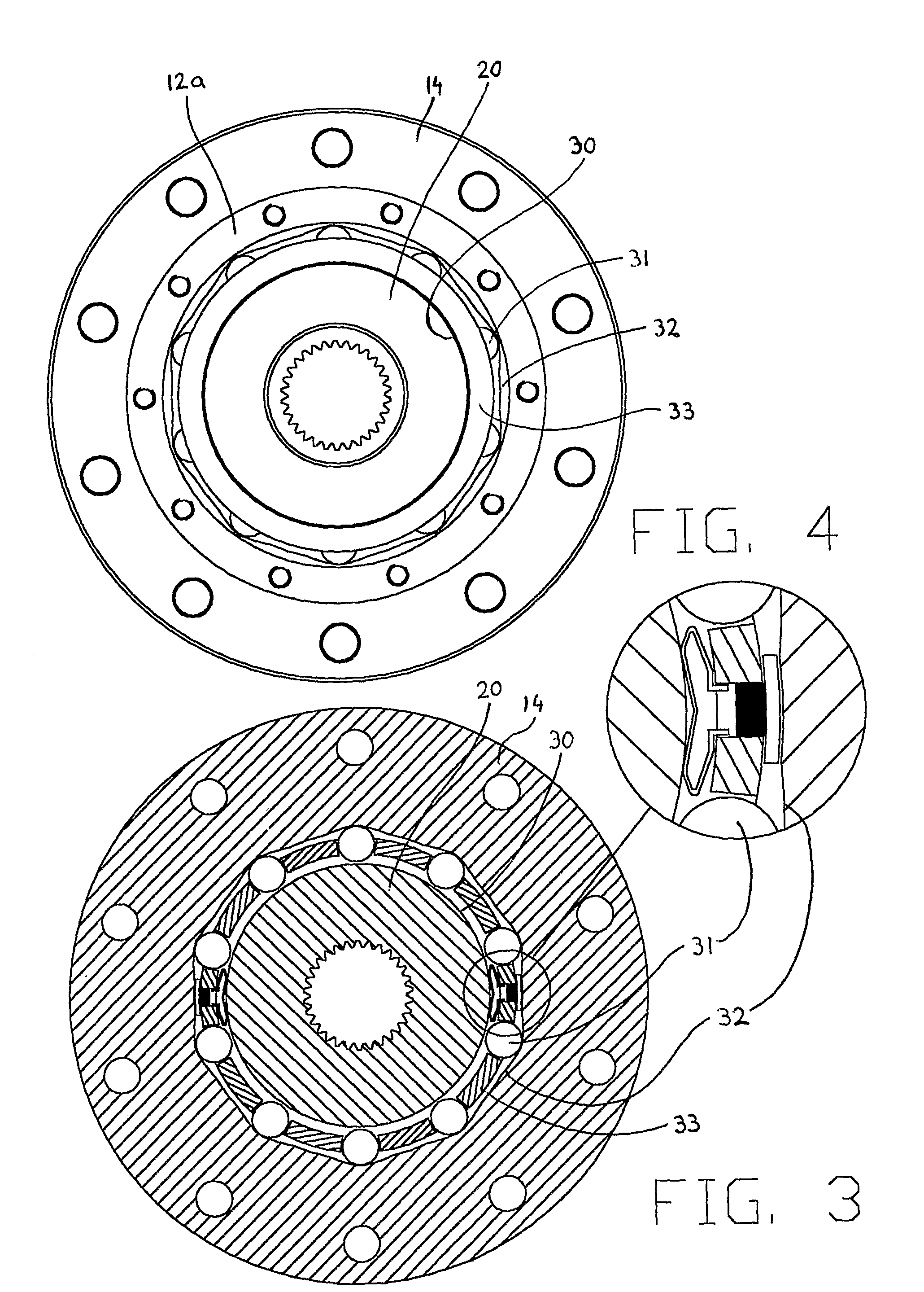
[0054]Referring now to the drawings, which are not intended to limit the scope of the invention to the exact design shown, but rather to enable any person skilled in the art, to make use of its qualities.

[0055]FIGS. 1-18 shows in detail the preferred embodiments, which consist of an input shaft in the form of a differential cage 12 which consists of its main part 12a and its end cover 12b which together form a generally cylindrical body with an inner cavity 13. The outer surface of the cage 12 includes a flange 14 to, in a conventional way, accommodate a ring gear or the equivalent (not shown). The differential cage 12 also at each end includes a pair of hollow stub axles 16, 18. The inner and outer surfaces of said stub axles are both concentric to the rotational axis 9 of the differential cage 12. the inner cavity 13 of the differential cage 12 accommodates a pair of planetary wheels 28 and two output shafts in the form of the two side wheels (sun wheels) 20, 22. The output shafts...


PUM


Abstract

A differential gear is equipped with a selectively controllable locking device which is self energizing, i.e. it utilizes the differentiation energy to self-lock on its own accord. The control signal is therefore not needed to lock the locking device but rather to selectively, separately for each of the two possible differentiation directions, control it to not lock itself. This gives the differential gear four different working modes. These are: open regardless of differentiation direction; open in one differentiation direction but self-locking in the other direction; open in the other direction but self-locking in the first one; self locking regardless of differentiation direction. A control unit is supplied with sensor data of the present “driving situation”. The control unit has a steering strategy. With the right steering strategy it can regulate the control signal so as to permit the differential gear to equalize the torque at each output shaft for as long as possible but still to practically eliminate the risk of one wheel spin.

Description

CROSS REFERENCE TO RELATED APPLICATIONS[0001]This application is a national stage application of International Application PCT / SE2005 / 001483, filed 7 Oct. 2005, designating the United States of America, which claims the benefit of 0402448-5 filed 11 Oct. 2004.FIELD OF THE INVENTION[0002]The present invention relates to an apparatus for the distribution of the traction forces between the road wheels on each side of a motor vehicle (e.g. a car).DESCRIPTION OF THE RELATED ART[0003]The most common way to deal with this task is through the use of a conventional differential gear, or as it is more commonly known, an “open differential”. The open differential has been known for a long time, and it normally consists of some kind of planetary gear with one input shaft and two output shafts. The detailed layout can take one of several different forms but (by far) the most common form is the bevelled gear variant, in which both of the output shafts consists of bevelled gearwheels (sun wheels) ...

Claims


Application Information

Patent Timeline
Patent Type & Authority Patents(United States)
IPC IPC(8): B60W10/12F16HF16H48/08F16H48/10F16H48/11F16H48/16F16H48/20F16H48/24F16H48/295F16H48/30F16H48/34
CPCF16H48/08F16H48/10F16H48/11F16H48/16F16H48/24F16H48/30F16H48/34F16H48/295F16H48/20Y10T477/606F16H2048/201F16H2048/204F16H2048/346
Inventor ALFREDSON, JONAS LARS
Owner ALFREDSON JONAS LARS
Why Eureka
Try Eureka