Droplet discharge method, electro-optical device, and electronic device

a technology of electrooptical devices and droplets, applied in solid-state devices, chemical vapor deposition coatings, coatings, etc., can solve the problems of uneven density, long time-consuming overall discharge process, and decrease in contras

Active Publication Date: 2010-02-02
KATEEVA
View PDF8 Cites 2 Cited by
  • Summary
  • Abstract
  • Description
  • Claims
  • Application Information

AI Technical Summary

Benefits of technology

[0011]It is an advantage of the present invention to provide a droplet discharge method, an electro-optical device, and an electronic device, with which there is less unintended mixing of functional liquids, and in particular less mixing of functional liquids of different types.
[0012]To achieve the above mentioned object and other objects of the present invention, the droplet discharge method in accordance with a first aspect to the present invention is a droplet discharge method in which a discharge head and a substrate are scanned relative to each other while droplets of a functional liquid are discharged onto the substrate. The discharge head discharges a plurality of types of functional liquid. The substrate is provided with a plurality of prescribed portions for holding the discharged functional liquid. The discharge head and the substrate provided with the prescribed portions are scanned a plurality of times relative to each other, and in the plurality of scans, a full discharge scan, in which the functional liquid is discharged over the entire region of the prescribed portions, is performed at least one time for each of the prescribed portions, and a partial discharge scan is performed, in which the functional liquid is discharged so as to avoid at least part of the peripheral edges of the prescribed portions in scanning other than the full discharge scan.
[0013]With this arrangement, since a partial discharge scan is performed in which the functional liquid is discharged so as to avoid at least part of the peripheral edges of the prescribed portions in scanning other than the full discharge scan, droplets of functional liquid are prevented from landing around the peripheral edges of the prescribed portions. This prevents the functional liquid from splashing out from around the peripheral edges of the prescribed portions, and as a result much less of the functional liquid itself is splashed out from the prescribed portions, so there is less mixing of functional liquids of different types. Furthermore, since a full discharge scan is performed at least one time for each of the prescribed portions out of the plurality of scans, there is no uneven distribution of the functional liquid in the prescribed portions, and the functional liquid uniformly wets and spreads out over the entire prescribed portion.
[0014]It is preferable that, in the partial discharge scan, the functional liquid is discharged so as to avoid all of the peripheral edges of the prescribed portions.
[0015]With this arrangement, since the droplets of functional liquid are discharged so as to avoid all of the peripheral edges of the prescribed portions, even if the functional liquid should rebound upon landing, sufficient distance is ensured around the prescribed portions by these peripheral edges, so there is almost no splashing of the rebounding functional liquid out of the prescribed portions. Thus, there is less mixing of functional liquids of different types.
[0016]Also, it is preferable that the full discharge scan is performed at the beginning of all scans.

Problems solved by technology

When the apparatus discussed in the above mentioned reference is used, however, since a plurality of types of functional liquid are discharged onto the substrate by different devices one at a time, the overall discharge process ends up taking a long time.
Also, the prescribed portions provided to the substrate usually have a larger volume than the droplets of functional liquid, and cannot be fully filled with functional liquid in a single scan, so scanning is performed a number of times. Further, since the prescribed portions have a large bottom surface area compared to the size of the droplets of functional liquid, in each scan the functional liquid is discharged evenly over the entire bottom surface of the prescribed portions so that the functional liquid will not be distributed unevenly within the prescribed portions.
If functional liquids of different types become mixed in an electro-optical device, this can lead to a decrease in contrast.
Also, even if functional liquids of the same type become mixed, the targeted prescribed portions may end up not holding the intended amounts of functional liquid, which causes density unevenness.

Method used


Image

  • Droplet discharge method, electro-optical device, and electronic device
  • Droplet discharge method, electro-optical device, and electronic device
  • Droplet discharge method, electro-optical device, and electronic device

Examples


Embodiment Construction

[0054]Selected embodiments of the present invention will now be explained with reference to the drawings. It will be apparent to those skilled in the art from this disclosure that the following descriptions of the embodiments of the present invention are provided for illustration only and not for the purpose of limiting the invention as defined by the appended claims and their equivalents. In the drawings, the scale is varied as necessary to show each of the members large enough to be recognized.

Electro-Optical Device

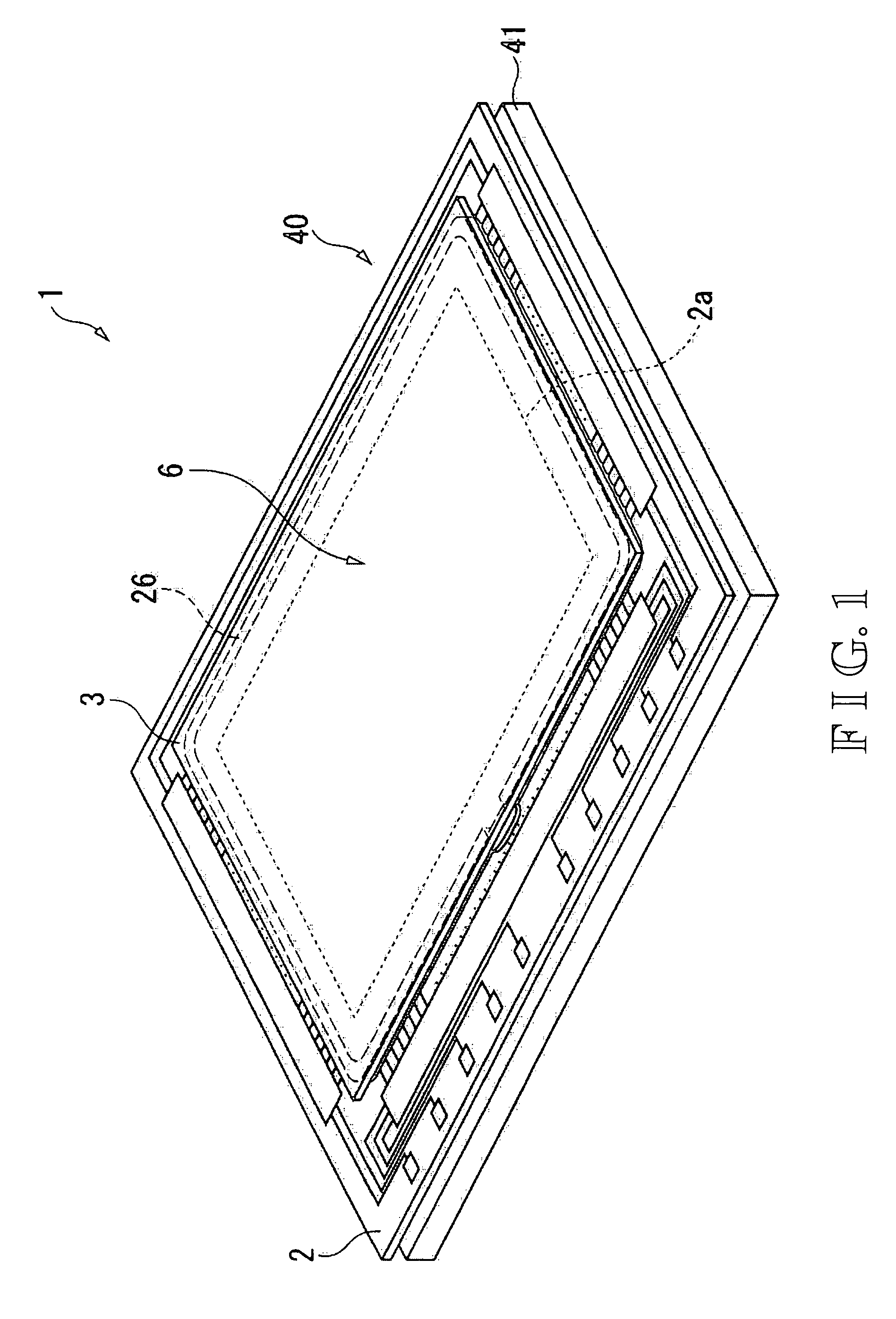
[0055]FIG. 1 is a perspective view of a liquid crystal device 1 in accordance with this embodiment. As shown in FIG. 1, the liquid crystal device 1 includes a liquid crystal panel 40 and a backlight 41. The liquid crystal panel 40 comprises an active matrix substrate 2 and a color filter substrate 3 that are stuck together with a sealing material 26 therebetween, and liquid crystals are sandwiched between the active matrix substrate 2, the color filter substrate 3, and ...


PUM

PropertyMeasurementUnit
lengthaaaaaaaaaa
lengthaaaaaaaaaa
diameteraaaaaaaaaa

Abstract

A droplet discharge method includes performing a plurality of scans in which a discharge head and a substrate are scanned relative to each other, and discharging droplets of a plurality of types of functional liquid from the discharge head onto a plurality of prescribed portions on the substrate configured and arranged to hold the discharged functional liquid while the discharge head and the substrate are scanned. The performing of the plurality of scans includes performing at least one full discharge scan for each of the prescribed portions so that the functional liquid is discharged over an entire region of each of the prescribed portions, and performing a partial discharge scan so that the functional liquid is discharged so as to avoid at least part of peripheral edges of the prescribed portions.

Description

CROSS-REFERENCE TO RELATED APPLICATIONS[0001]This application claims priority to Japanese Patent Application Nos. 2005-184456 and 2006-101642. The entire disclosures of Japanese Patent Application Nos. 2005-184456 and 2006-101642 are hereby incorporated herein by reference.BACKGROUND[0002]1. Technical Field[0003]The present invention relates to a droplet discharge method, an electro-optical device, and an electronic device.[0004]2. Related Art[0005]The droplet discharge head of an inkjet printer is able to discharge microscopic ink droplets in the form of dots, which affords extremely high precision in terms of the uniformity of the size and pitch of the ink droplets. This technology has been applied to the manufacture of many different products, such as electro-optical devices. For instance, it can be applied in the formation of a film for the light-emitting components of organic EL display devices or the color filter layers of liquid crystal devices.[0006]More specifically, a drop...

Claims


Application Information

Patent Timeline
Patent Type & Authority Patents(United States)
IPC IPC(8): B05D5/12
CPCH01L51/0005H01L51/56H10K71/135H10K71/00B05C5/02B05C9/06
Inventor NAGAE, NOBUAKIARUGA, KAZUMI
Owner KATEEVA
Why Eureka
Try Eureka